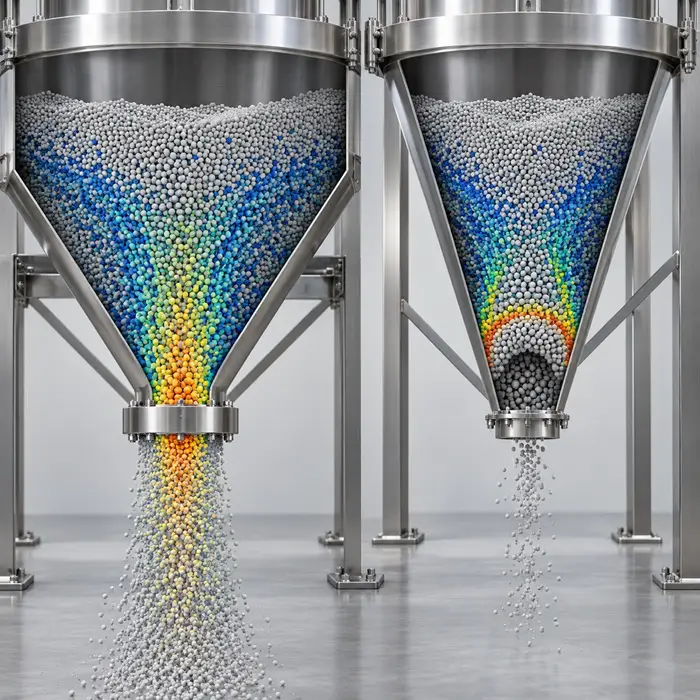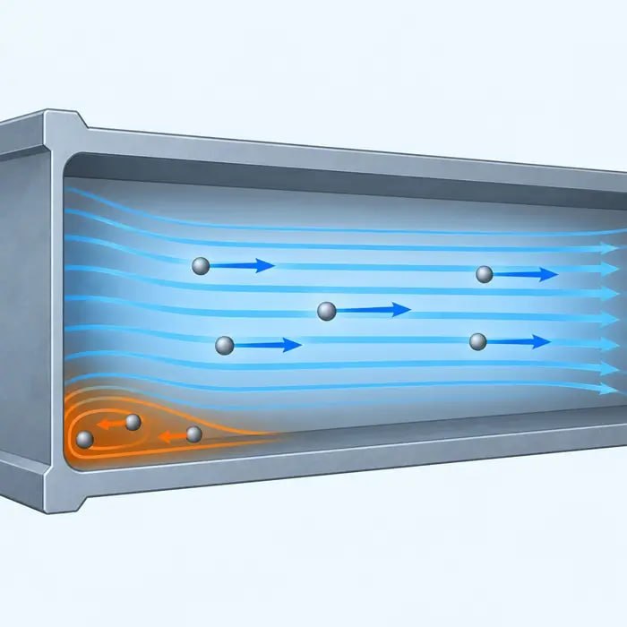

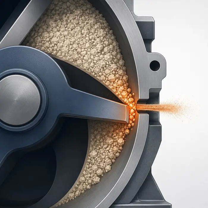
A rotary airlock sits at a pressure boundary. Its function is to transfer powder from a near-atmospheric hopper into a pneumatic conveying line while limiting gas flow across that boundary. As the rotor turns, each pocket fills at the inlet, moves through the housing, and discharges into the conveying stream. Leakage can occur through radial tip clearances, axial end clearances and gas carried upward in returning rotor pockets, while the moving vanes can also expose particles to crushing, impact and shear.
Leakage and attrition can occur in the same valve, but their relative importance is not determined by tip clearance alone. Attrition depends on particle strength, particle size relative to the moving gap, rotor speed, solids loading, and local material accumulation. Leakage depends on pressure differential, radial and axial clearances, product head, venting, and valve geometry. Because routine monitoring rarely separates these mechanisms, valve condition can be overlooked when a downstream particle size distribution begins to drift.
How Clearance Influences Leakage and Attrition
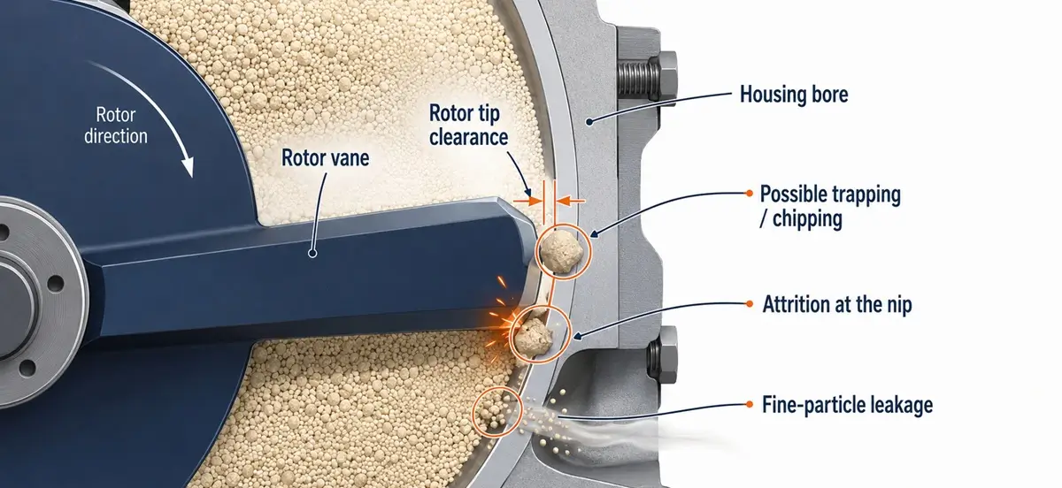
The radial clearance between the rotor vane tips and the valve bore must be small enough to restrict gas leakage while allowing for manufacturing tolerances, thermal expansion, rotor deflection, and product deposits. Wear generally increases the available leakage area. The effect on attrition is less direct because particle breakage can increase or decrease as the gap changes relative to particle size. Small-clearance studies have found distinct attrition maxima when gap width approaches particular multiples of particle diameter, so a wider gap does not automatically produce less damage.
When clearance is tight, particles approaching the gap dimension can be caught and fractured as the rotor tip sweeps past the bore. Coated granules and structured particles are especially vulnerable because surface damage occurs before any detectable shift in bulk particle size. This follows the pattern described for coated particle damage preceding core fracture: coating failure is not visible in standard PSD monitoring until the damage has already progressed. The same principle applies to any structured or surface-modified material passing through a rotary valve nip.
Differential Pressure Drives Fine-Particle Back-Flow
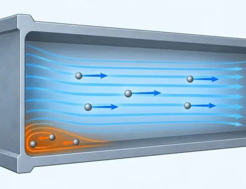
In a positive-pressure conveying arrangement, the conveying line downstream runs at higher pressure than the hopper above. This pressure differential drives reverse airflow through the clearance gap. The bypass air can entrain fine particles as it flows toward the low-pressure side. Fines are preferentially transported because their drag-to-inertia ratio is high: reverse airflow that cannot mobilize a coarse particle may still carry fine fractions upward without difficulty.
The practical result can be fine-fraction enrichment in the upstream vessel and corresponding depletion in the conveyed product. In vacuum conveying, the direction reverses: the conveying line is at lower pressure, so air and fines travel downward into the stream rather than back into the hopper. Either way, the effect is directional and cumulative. Why small amounts of fines produce disproportionate effects on powder behavior is useful context for understanding what this selective depletion does to downstream process performance.
Why Worn Clearance Looks Like Upstream Process Drift
As tip clearance widens over months of service, bypass volume generally increases and may produce more pronounced fine-fraction depletion downstream. A particle size distribution measured at the product point may show a rising D10 and reduced fines content if selective fines migration dominates. If attrition dominates, however, the fine fraction may increase instead, so the full distribution should be reviewed before the shift is attributed to upstream milling or classification.
Investigations typically start upstream and find nothing, because the variable that changed is the valve. The gradual pace of wear makes individual batch comparisons uninformative. Trend analysis over longer periods reveals the drift, but only if particle size data is reviewed in process context and compared against valve maintenance records. Without that cross-reference, the valve is never on the suspect list.
Upstream Signals That Predict Valve Degradation
Three monitoring points give advance warning before any downstream quality threshold is crossed. In a positive-pressure system, fines accumulation in the upstream hopper is the earliest indicator. Bypass flow deposits entrained fines in the vessel above the valve, visible during inspection as gradual enrichment at the hopper base. A rising difference between tapped density at the hopper outlet and downstream discharge can support the fine-accumulation hypothesis, although PSD measurements are needed to confirm it.
Conveying-system trends provide a second signal. As clearance widens, increased leakage may alter the pressure differential, available conveying airflow, blower demand or vent loading, depending on how the system is controlled. These changes may become visible in long-term operating records even when individual batch data appears normal.
Particle size monitoring at the valve inlet provides the most direct indicator. If fines are enriching upstream while the downstream PSD shifts coarser, the valve is the most probable source. Comparing inlet and outlet PSD at two or three maintenance intervals establishes a performance baseline and flags degradation before it reaches a specification limit. As discussed in the context of pneumatic conveying attrition, the rotary valve is often the least monitored site in a conveying system despite being present at every pressure-boundary handoff.