
🔑 Key Takeaway
Ribbon solid fraction, the envelope density of the ribbon divided by the true density of the powder, is set by how much powder mass is consolidated per unit of ribbon produced, not by the roll force setpoint. Mass feed rate, roll speed, gap response, and the powder’s friction and deformation behavior at the nip all contribute to that outcome, and each can shift between lots that pass incoming release testing. The practical consequence is that a screw-to-roll speed ratio held constant does not guarantee a constant mass delivery, and a roll force held constant does not guarantee a constant degree of consolidation. Measured ribbon solid fraction, taken in line or on the bench, is a more direct decision input for interpreting granule strength and tablet performance than an incoming flowability specification, which characterizes the powder before it reaches the roll gap.

Two lots of the same powder, run at the same roll force setpoint on the same roller compactor, sometimes produce ribbons that mill into granules with noticeably different strength and different tablet compression behavior downstream. The incoming powder passed its flowability acceptance criteria in both cases. Nothing on the certificate of analysis flags a difference. The operator is left adjusting compression force on the tablet press to compensate for a granule population that was never characterized at the point where the variability was introduced.
The missing information is not necessarily absent from the powder. It is absent from the incoming flowability result, which does not capture the feeding and densification response the powder produces inside the roller compactor. Specific compaction force is one input among several that set the final ribbon solid fraction. How much powder mass the feed screw actually delivers per roll revolution, how long that material spends under load at the running roll speed, and how far up the roll circumference it stops slipping and starts compacting all determine what the material experiences. Each of those can shift between lots while the force reading on the panel stays where it was set.
Roll Force Sets Line Load, Not Solid Fraction
Specific compaction force is the applied roll force normalized by roll width, usually reported in kN/cm. It is a line load rather than a pressure. The actual pressure the powder experiences at the roll surface depends on the contact geometry at the nip, which itself varies with gap and with where compaction begins on the roll circumference, so two runs at the same specific compaction force do not necessarily apply the same pressure to the material. Holding the setpoint constant fixes the force per unit of roll width. It does not fix how much powder mass is present when that force is applied, how long the material is under load, or at what angular position on the roll it begins to be compacted rather than dragged. Ribbon solid fraction is the response to all of those acting together.
It is worth separating solid fraction from ribbon density here because the two are often used interchangeably, and only solid fraction normalizes the measured density against true-density differences between lots. Envelope density is the measured mass of the ribbon divided by its enclosed volume. Solid fraction is that envelope density divided by the true density of the powder blend. Two lots differing in polymorphic form, moisture content, or excipient ratio can carry different true densities, in which case an identical envelope density reading corresponds to a different degree of consolidation. Since porosity, and therefore granule strength, tracks solid fraction rather than envelope density, solid fraction is the quantity worth trending across batches.
Control mode matters here, because it determines which variables the operator sets and which ones respond. In one common arrangement, the operator sets roll force and feed screw speed, and the gap width floats to whatever position the incoming mass flow supports. In another, the gap is the controlled target and the system modulates feed screw speed to hold it while force is maintained at setpoint, which means the screw speed becomes a response variable rather than a setting. Roll speed remains an independent operating variable in both cases and changes the residence time under load. Which architecture is in use changes how a given reading should be read. A drifting gap at stable force is direct evidence of a mass flow change in the first arrangement, while in the second the equivalent evidence is a drifting screw speed at stable gap.
Mass Delivery, Not the Speed Ratio, Governs What Reaches the Nip
The feed screw speed relative to the roll speed, commonly expressed as the screw-to-roll speed ratio, is the setting most often used to control how much powder is delivered into the nip per unit of ribbon produced. A higher ratio feeds more powder relative to roll rotation, increasing mass throughput and tending to produce a denser, thicker ribbon at a given roll force. A lower ratio starves the compaction zone, producing a thinner, less consolidated ribbon even though the roll force reading has not changed. Published work on the screw-to-roll speed ratio reports that ribbon porosity decreases approximately linearly with increasing ratio over the range studied, accompanied by an increase in roll gap and mass throughput. That linear description applies within the range tested, since the response tends to flatten once the nip is fully fed and additional feed is rejected back up the screw.
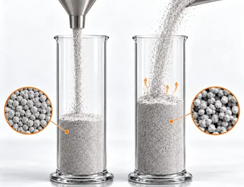
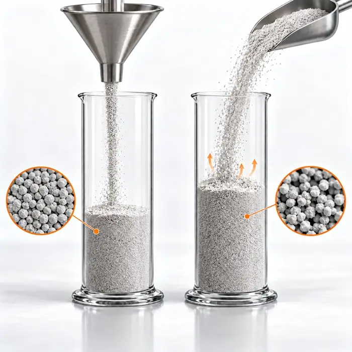
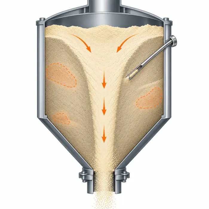
The point that matters between batches is that the ratio is a kinematic setting, screw revolutions per roll revolution, and not a measure of mass. At a fixed screw-to-roll speed ratio, powder delivery can still change because the screw is no longer transporting the same mass per revolution. Screw wear increases clearance and reduces the volume conveyed. Hopper fill level and refill timing change the stress state above the screw inlet and therefore the bulk density of the powder where it is picked up. A recent refill can leave material temporarily aerated and reduce the mass conveyed, or it can densify the powder at the screw interface and force more into the flights, so the direction depends on the powder and the refill dynamics rather than being fixed. Lots arriving with different aerated or tapped bulk density will also fill the screw flights differently at the same speed. In each case, the numerical ratio logged for the batch is unchanged while the mass entering the nip is not, which is why two batches recorded at identical force and identical ratio can still produce ribbons of different solid fraction.
The Material Side: Nip Angle and Wall Friction
Mass delivery explains part of the lot-to-lot variation. The rest tends to sit in how the powder interacts with the roll surface itself. Powder entering the region above the nip initially slips against the rotating rolls. At some angular position, it stops slipping and begins to be carried and compacted with the roll surface. That position is the nip angle, and it marks where meaningful densification starts. A larger nip angle means the material is under compressive load through a greater portion of the roll rotation and typically exits at a higher solid fraction for the same applied force.
Johanson’s rolling theory remains the standard framework for estimating this angle, and it takes three material inputs: the effective angle of internal friction, the wall friction angle measured against the actual roll surface material, and the compressibility constant describing how the powder’s bulk density responds to applied pressure. All three can vary between lots that pass a conventional release specification. A shift in particle size distribution changes the effective angle of internal friction. A change in lubricant level or in how evenly the lubricant is distributed changes wall friction against the roll, sometimes substantially, since lubricant tends to concentrate at the interface. Moisture affects both. Roll surface condition matters on the equipment side, since knurling wear or polishing over a campaign changes the same wall friction term.
A second material-side mechanism worth checking is air removal. Powder entering the nip carries interstitial air that has to escape countercurrent through the incoming feed. At higher roll speeds, the residence time in the compaction zone shortens, and lots with a higher fines content are less permeable and vent more slowly. Where air is trapped, the achievable solid fraction is limited, and the ribbon may show lamination or edge splitting that mills into an unusually broad granule size distribution.
Why This Escapes a Standard Incoming Flowability Spec
An incoming acceptance test based on Hausner ratio or Carr index characterizes how loosely consolidated powder rearranges under tapping. It says little about how that same powder will densify under a specific combination of applied force, mass feed rate, roll speed, and roll surface, because that response is a process-dependent outcome rather than a fixed material property. A powder can sit comfortably inside a Hausner ratio specification and still produce a different ribbon solid fraction if the screw delivers it at a different effective mass rate, or if its deformation behavior under the applied load differs from the reference lot used to set the specification, a mechanism explored further in relation to powder deformation behavior under pressure.
Shear cell characterization is a different case and deserves separating out. A flow function from a ring or Jenike shear cell describes bulk failure behavior under known consolidation, and a wall friction test run against a coupon of the actual roll surface material produces the wall friction angle directly. Those two outputs, together with a compressibility relationship from the same instrument, are the inputs Johanson’s model needs. Shear cell data is therefore not merely a handling indicator in this context. It is the closest thing available to a predictive material characterization for the nip. The limitation is one of how the test is usually specified rather than what it can measure, since most incoming specs call for a flow function index and stop there.
Measuring Ribbon Solid Fraction as a Decision Input
Measuring the ribbon itself gives a closer read on the variable that links to granule strength and tablet performance, and it does not necessarily require in-line instrumentation.
The benchtop route is usually the first one worth trying. Cut a section of ribbon of known length, measure its width and its thickness at several positions across the face with a micrometer, weigh it, and calculate envelope density from mass over volume. This introduces geometric bias because the ribbon cross-section is neither perfectly rectangular nor uniform across its width, so the method is better suited to comparative trending between batches than to determining an absolute solid fraction. Where a more defensible number is needed, envelope density by dry powder displacement pycnometry handles irregular ribbon fragments without the geometric assumption. In either case, divide by the true density measured by helium pycnometry on the same blend to get solid fraction.
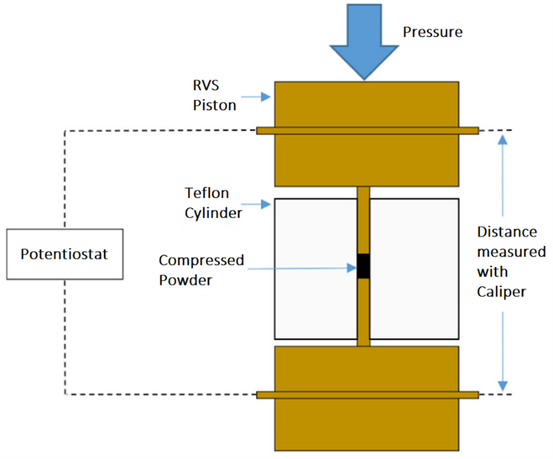
In-line measurement is worth the capital where the process runs continuously or where release depends on it. Near-infrared monitoring of roller compacted ribbon density has been demonstrated for real-time tracking, correlating spectral response to density variation as the process runs. A compaction simulator or instrumented tablet press sits alongside this rather than substituting for it. Running representative slugs relates applied load to resulting solid fraction under controlled conditions, which is useful for screening materials and for building the compressibility relationship a nip angle estimate needs. It does not reproduce screw feeding, nip entry, roll surface friction, the shear conditions at the rolls, or the transverse density distribution across a real ribbon, so it informs interpretation rather than replacing a measurement on the ribbon itself.
Whichever route is used, the measurement functions as a decision input rather than a standalone release criterion. Solid fraction varies across the width and thickness of a single ribbon, with more consolidated material near the center and looser material near the edges, so a single probe position or a single cut sample does not fully describe mechanical uniformity. As with other bulk measurements, an average value can mask meaningful local variation, a limitation discussed more broadly in the context of bulk density interpretation. Solid fraction trends still need confirming against measured granule strength after milling and against tablet performance at the press, since ribbon tensile strength, milling conditions, transverse density distribution, and lubrication all contribute to what arrives at the tablet press. The value of the measurement is that it locates a process shift closer to its source than an incoming acceptance test can, not that it predicts downstream performance on its own.
Denser Ribbon Is Not Automatically Better
One point is worth stating plainly before solid fraction becomes a target rather than a monitored variable. Increasing ribbon solid fraction tends to produce stronger, less friable granules with better flow, but it can reduce the tablet tensile strength achievable from those granules at a given compression force. The effect is well documented for plastically deforming excipients, microcrystalline cellulose in particular, and is usually attributed to work hardening: the material deforms irreversibly in the nip, and that deformation is not available again during tablet compression, leaving less capacity for interparticulate bonding at the press.
This means compressibility and compactibility can move in opposite directions. The granule may compress readily into a low-porosity tablet while producing a weaker compact than the ungranulated blend would have. Where tablet hardness has been drifting downward and the response has been to increase compression force, a rising ribbon solid fraction is a plausible contributing cause rather than a solution. The practical implication is that solid fraction usually has a working window with limits at both ends, and the window tends to be blend-specific.
Practical Indicators of Ribbon Solid Fraction Drift
Where granule strength or tablet performance varies despite powder that passed incoming release testing, the following are worth checking before adjusting the press.
Compare actual mass throughput between batches rather than the speed ratio alone. The ratio can be identical in both records while the mass delivered per screw revolution is not, and throughput is the quantity that links to consolidation.
Check ribbon mass per unit length. Weighing a cut length of ribbon of known dimension is the most direct available read on how much material the nip is receiving per roll revolution, and it requires no instrumentation beyond a balance and a rule.
Review feed screw torque or drive load where it is logged. A change in torque at unchanged screw speed indicates that the screw is working against a different material loading, which is often the earliest sign that filling efficiency has shifted.
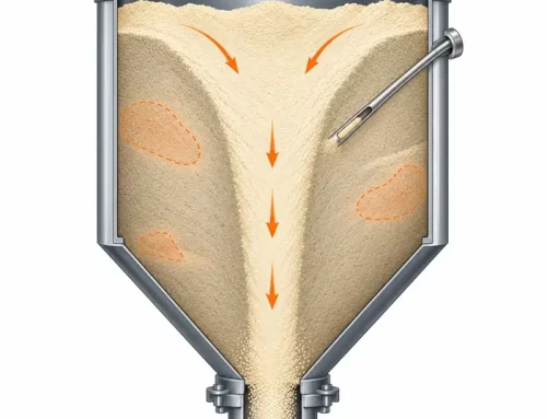
Check whether hopper fill level or refill timing changed. Fill level alters the stress state above the screw inlet and therefore the bulk density of the powder where it is picked up, and the direction is not fixed. A refill can leave material temporarily aerated and reduce the mass delivered per revolution, or it can densify the powder at the screw interface and force more into the flights than the setpoint assumes. Both show up as a mass delivery shift at unchanged screw speed, which is covered further in relation to permeability-driven dosing instability.
Review the gap and screw speed traces together rather than either alone. Under force control with a floating roll, a widening gap at constant force is direct evidence of a mass flow change. Under gap control, the equivalent evidence is the screw speed the system had to run to hold that gap.
Compare lubricant level and blend time between the two lots. Both affect wall friction against the roll surface and therefore the nip angle, without necessarily showing up in a conventional flowability result.
Check the fines fraction in the incoming lots. Lower permeability slows countercurrent air escape at the nip and can limit achievable solid fraction at higher roll speeds.
Trend measured ribbon solid fraction against the batches that produced weak or overly hard granules, rather than relying on the roll force chart alone. A benchtop mass and dimension measurement on retained ribbon is often enough to establish whether there was a real difference.
Where Ribbon Solid Fraction Sits in the Wider Picture
Ribbon solid fraction sits at the junction of two mechanisms covered elsewhere on this site: how a powder consolidates under applied pressure, and how bulk measurements average over local variation. The related material on powder deformation behavior under pressure and on bulk density interpretation covers the underlying principles in more detail.