

A pneumatic conveying line can look healthy from an operations perspective. The material moves, the receiver fills, and no alarm appears. Then something changes downstream. The powder may dust more during discharge, feed less steadily, or exhibit a broader particle-size distribution than expected. That pattern is common, and it is one reason pneumatic conveying attrition is often missed in troubleshooting. The transfer appears successful, so the line escapes scrutiny.
That is the wrong assumption. In dilute-phase conveying, especially, particles experience repeated acceleration, redirection, and collision. Review work in Powder Technology identifies particle attrition as a key pneumatic conveying phenomenon, and classic conveying studies show that impact and shear loads, particularly at bends, drive breakage and chipping. Air velocity, particle velocity, loading ratio, bend structure, and particle properties all matter.
Why the line can “work” while the powder changes
The operational definition of success is often too narrow; the powder reaches the destination, and the transfer gets marked as acceptable. However, that tells you only that the system moved material. It does not tell you that the powder arrived unchanged. Kalman’s conveying work states this point clearly: pneumatic lines should not always be viewed as passive necessities, because they can also act as processing devices through comminution and related effects.
That matters because a modest amount of breakage can stay invisible during transfer and still become obvious later. A small fines increase may not affect receiver fill. It may show up at the next step instead, where it changes dust release, feeder stability, blend segregation risk, filter loading, or bulk density response. Segregation research in tablet manufacturing, for example, shows that initially acceptable blends can lose uniformity during transfer and handling, not only during mixing. That logic extends well beyond pharma. Once conveying changes the particle population, downstream behavior can shift even when the line itself looks uneventful.
Where pneumatic conveying attrition usually starts
Bends and the number of bends remain the first place to look. The flow direction changes there, so particles experience high local impact loads and wall interactions. Kalman’s attrition-control paper says the main attrition in pneumatic conveying had long been observed at bends, and the study focuses on bend structure precisely because the particle loads intensify there.
Velocity is the next major lever. The same paper cites prior work showing that air velocity has a prime effect on attrition rate, while loading ratio and bend structure still matter. That makes sense mechanically. Higher relative velocities increase collision energy. If the material is brittle, friable, or already carrying weak agglomerates, the breakage threshold is reached more easily.
Repeated passes also matter. Attrition is not always a one-hit event. It can accumulate over time or across loops, which is why materials that survive one trial run can still drift during sustained production. Experimental work on repeated pneumatic transport of granules and powders has documented progressive change in size distribution under repeated conveying exposure.
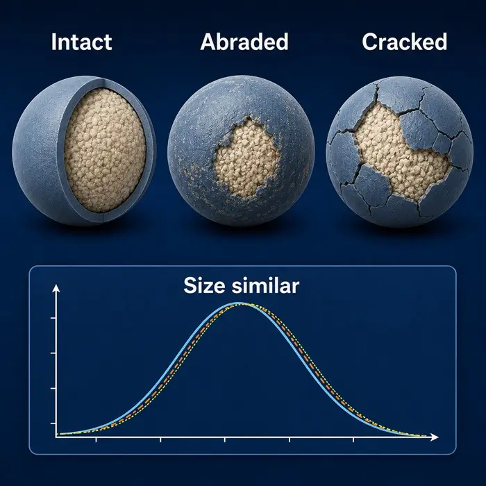
What changes first when attrition starts
The first visible change is often more fines. That sounds obvious, but the practical consequence is broader than a single sieve fraction. Once fines increase, the material’s surface area balance, packing response, air interaction, and contact behavior can all shift dramatically. A powder that originally fed cleanly may begin to flood, pulse, or stick more readily depending on the rest of the formulation and process window. That is an engineering inference, but it follows directly from the known link between changed particle populations and changed downstream handling behavior.
PSD broadening is another common signal. In some materials, corners chip rather than whole particles shatter. In others, granules break more extensively. The effect depends on particle strength, shape, and internal structure. Kalman’s paper distinguishes breakage from chipping and links both to conveying conditions and material properties.
Then there is hidden functional damage. A pharmaceutical continuous-manufacturing study found that pneumatic transport after twin-screw granulation caused extensive breakage in wet granules, while a later dry transfer line caused additional extensive breakage and attrition. Importantly, the drying phase itself caused far less damage. In other words, the transfer step changed granule quality more than the process stage many people would instinctively blame first.
A practical plant example
Imagine a powder blend that leaves the mixer in spec and reaches the day bin without any obvious issue. The conveying line runs in a dilute phase through several bends. No plugging occurs. No one sees a dramatic upset. Later, the bagging station shows more visible dust, and the feeder becomes less steady than usual.
That sequence does not automatically prove pneumatic conveying attrition, but it is exactly the pattern that should trigger the question. The transfer step may have generated enough fines or agglomerate damage to shift how the powder detaches, entrains, or packs. By the time operations notices the effect, the conveying event is already over, so the cause gets misassigned to storage, humidity, or feeder settings. Sometimes those factors do contribute. However, the line itself may have been the first point of quality drift.
How to check whether the line is changing the powder
Start with before-and-after sampling. Do not rely on one sample from the receiver. Compare the feed point with the discharge point under normal operating conditions. Then look for PSD shift, fines increase, or shape change if the material justifies image analysis. If dust complaints exist, compare dustiness or airborne-release tendency before and after transfer as well.
Next, map the geometry. Count bends. Check their type. Review velocity targets and loading ratio. Kalman’s work and later review literature both point to those variables as major attrition drivers. If the line was sized mainly for throughput or blockage avoidance, product preservation may never have been optimized.
Then check where the evidence appears. If filter loading rose, if dust increased at discharge, or if feeder behavior changed after a line modification, those are useful clues. They do not replace particle characterization, but they tell you where to focus. The line may be eroding the powder, not just carrying it.
The useful conclusion
The main mistake that occurs all too often is to treat a conveying line as neutral until it plugs.
For sensitive materials, that mindset is too crude. Pneumatic conveying attrition can change the powder long before the system shows a classic transport failure. Bends, velocity, repeated collisions, and fragile particle structure can quietly create fines and shift downstream behavior. Therefore, when the material arrives but performs differently, the right question is not only whether the line conveyed it. The better question is whether the line changed it.
That is the engineering value of this topic. It moves troubleshooting upstream. Instead of blaming the feeder, the storage bin, or the operator by default, you test the transfer step itself. In many plants, that is where the drift began.


