
🔑 Key Takeaway
Dense-phase and dilute-phase pneumatic conveying create different particle contact mechanics, not just different pressure drops. Dilute-phase systems run at higher velocity with particles suspended in the gas stream, so particle-wall impact at bends is usually the dominant attrition driver. Dense-phase systems move powder at lower velocity and higher solids loading, which cuts impact frequency but can introduce particle-particle compression and shear inside moving plugs. The choice between them is constrained before attrition ever enters the discussion: conventional dense-phase transport generally requires a powder that either retains air well or is permeable enough to let plugs move without excessive pressure buildup, and many industrial granular materials sit outside both windows without assisted equipment. Where both modes remain available, the safer one should be confirmed with attrition, particle size distribution, permeability, and bulk density data rather than assumed from mode alone.
Table of contents

A receiving vessel yields a powder with a fines fraction that was not present in the feed hopper or a first drum off a campaign that does not match the last. The conveying line is the usual place to look, and the usual response is to reconsider dense-phase versus dilute-phase transport. That decision is normally driven by throughput targets, line length, and plant layout, which are real constraints, but they leave out the variable that determines whether the powder arrives in the condition it left: the contact mechanics inside the pipe. Dense-phase and dilute-phase systems do not simply move bulk solids at different speeds. They expose particles to different combinations of particle-particle contact and particle-wall contact, and those contact patterns are what drive attrition and segregation outcomes.
This distinction matters most for friable granules, coated particles, agglomerates, and any formulation where fines generation changes downstream behavior, whether that behavior is dissolution rate, coating integrity, or flow function at the next unit operation. The assumption that dense-phase conveying is always the gentler option, or that dilute-phase is only a bulk-throughput compromise, does not hold across all materials. It also assumes a choice that may not exist, since dense-phase suitability is a property of the powder before it is a design preference. The sections below work through the contact mechanisms, the operating variables that control them, the material properties that limit the available options, and the test data that can turn conveying mode selection from a rule of thumb into an evidence-based decision. Background on conveying system design is covered in Pneumatic Conveying of Bulk Solids.
Dense Phase and Dilute Phase at a Glance
The two modes sit at opposite ends of a velocity and solids loading spectrum, and the ranges below are the working conventions rather than sharp boundaries.
| Parameter | Dilute phase | Dense phase |
|---|---|---|
| Conveying velocity | Roughly 15 to 30 m/s | Roughly 1 to 8 m/s |
| Solids loading ratio | Typically below about 15 | Typically above about 15 |
| Flow structure | Particles fully suspended in gas | Plugs, slugs, or moving dunes |
| Line pressure | Low pressure, high volume | High pressure, low volume |
| Dominant contact | Particle to wall, concentrated at bends | Particle to particle, inside the plug |
| Powder requirement | Few restrictions | Good air retention or high permeability |
| Typical wear mode | Bend erosion, impact attrition | Compression and shear, line plugging |
Two Conveying Regimes, Two Contact Mechanisms
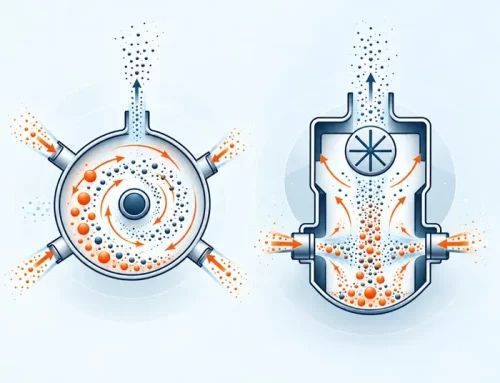
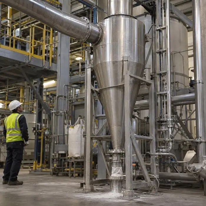
In dilute-phase conveying, particles are fully suspended in the gas stream and travel at velocities usually well above the material’s minimum conveying velocity. Because the particles are dispersed rather than clustered, the contact events that matter most happen between particles and the pipe wall, and they concentrate at geometric discontinuities such as bends, tees, and diverter valves where the flow direction changes abruptly. That contact is largely impact-driven: a particle carrying kinetic energy proportional to its mass and velocity strikes a wall or a diverter surface, and the resulting stress can chip edges, fracture agglomerates, or damage a coating layer depending on the particle’s mechanical strength. The mechanism is discussed in more detail in Pneumatic Conveying Attrition: Transfer Quietly Changes Powder, and equipment-specific contact damage at rotary valves is covered in What Rotary Airlocks Actually Do to Powder.
Dense-phase conveying works on a different physical picture. Solids move as plugs, slugs, or moving dunes separated by air gaps, at velocities typically in the range of 1 to 8 m/s against 15 to 30 m/s for dilute-phase transport. Because the particles are packed together rather than dispersed, wall contact is less frequent and generally lower energy, but particle-particle contact inside the plug becomes the dominant mechanism. As a plug advances, particles within it experience compressive loading from neighboring particles and shear as the plug deforms around bends or through changes in pipe diameter. This does not automatically make dense-phase gentler; it changes which contact type dominates, and whether that trade favors the powder depends on whether the material is more vulnerable to impact fracture or to compressive and shear damage.
Not Every Powder Can Be Conveyed in Dense Phase
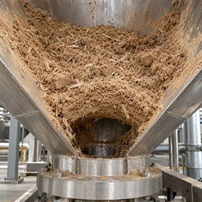
Whether a powder can be conveyed in dense phase at all is a material property rather than a design choice. Stable plug flow generally requires either good air retention, characteristic of fine, aeratable powders that hold interstitial gas long enough to keep the plug mobile, or high permeability, characteristic of coarse, free-draining granular materials that allow gas to pass through the plug rather than compress it. Powders that fall between these behaviors, which include a large share of intermediate-size granular products, tend to form plugs that consolidate and stall, producing line blockages rather than transport. Dense-phase conveying of these materials is usually possible only with assisted equipment such as a bypass pipe, air injection boosters, or plug-breaking devices, which changes both the capital cost and the contact mechanics of the comparison. Permeability and deaeration testing is therefore a gate on the decision, not a supporting measurement taken afterwards.
Why the Same Powder Can Behave Differently in Each Mode
A coated granule with a brittle shell but a resilient core may tolerate the sustained particle-particle pressure of a dense-phase plug reasonably well, since the coating is not subjected to sharp impact loading, yet the same granule can lose coating integrity quickly under dilute-phase bend impacts. A friable, low-density agglomerate can show the opposite pattern, surviving low-velocity dense-phase transport but breaking down when accelerated to dilute-phase velocities. This is why attrition sensitivity has to be evaluated for the specific material and its dominant failure mode, rather than inferred from a general reputation that one conveying mode is protective. Attrition that shows up as coating loss before any measurable change in particle size distribution is addressed in Coated Particle Damage Before Particle Size Changes.
Velocity and Solids Loading Ratio as the Operating Levers
Solids loading ratio, the mass ratio of conveyed solids to conveying gas, is one of the two variables engineers adjust to move between dilute-phase and dense-phase operation. As a general industry rule of thumb, loading ratios up to roughly 15 are typically associated with dilute-phase flow, while dense-phase operation is usually associated with loading ratios above that range, provided the conveying line velocity is kept below the threshold needed for dilute-phase transport, as summarized in ScienceDirect’s overview of dense-phase flow. This boundary is approximate and material-dependent rather than a fixed physical constant; particle size, shape, density, and pipe diameter all shift where the practical transition occurs for a given system.
The second lever is conveying velocity. In horizontal lines, the lower bound is set by the saltation velocity, the velocity at which suspended particles begin to settle out and form a moving bed along the pipe floor. The vertical equivalent is the choking velocity, at which the suspension collapses and the flow reverts to slugging. Minimum conveying velocity is set above these thresholds with a design margin rather than at them, and while values near 15 m/s are frequently cited for dilute-phase transport, the figure depends strongly on particle size, shape, and density, as outlined in ScienceDirect’s overview of minimum conveying air velocity. Operating above the minimum keeps the line from blocking, but every increment of velocity above it raises the kinetic energy of particle-wall impacts at bends, which is a documented contributor to erosive wear and particle attrition in dilute-phase bends, as shown in research on particle attrition and erosive bend wear in dilute-phase pneumatic conveying.
Reducing velocity and raising loading ratio to move toward dense-phase operation generally reduces impact frequency and impact energy, and pilot-scale and industrial experience often report that degradation increases at lower solids loading ratio or higher conveying velocity, consistent with an impact-dominated attrition mechanism. This does not mean the relationship runs in only one direction. For powders whose primary weakness is compressive or shear failure rather than impact fracture, an increase in loading ratio can raise particle-particle contact pressure inside the plug enough to offset the benefit of lower velocity. The correct operating point depends on which failure mode the material is actually prone to, which is a question for attrition test data rather than for a generic velocity-versus-loading rule.
Velocity Is Not Constant Along the Line
Velocity is not constant along a conveying line, and this is easy to overlook when a system is specified based solely on its pickup velocity. As the conveying gas moves toward the discharge end, it expands against falling pressure, its density drops, and its velocity rises accordingly. In a single-bore line, the velocity at the discharge can be two to three times the pickup velocity, which means the attrition and erosion exposure is concentrated in the final section of the pipeline and at the last bends before the receiver rather than distributed evenly along it.
Stepped-bore pipelines, which increase pipe diameter in one or more steps along the run, are the standard countermeasure, holding velocity inside a working window instead of allowing it to climb. Where attrition data indicates an impact-dominated failure mode, a stepped-bore dilute-phase line is often a more practical response than switching to dense-phase operation, which the powder may not support.
Segregation Mechanisms Differ Between the Two Modes
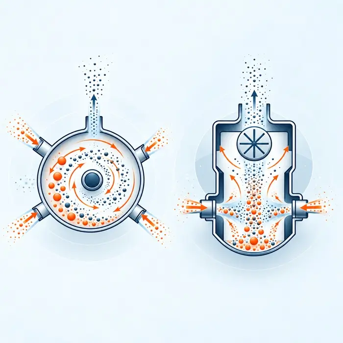
Dilute-phase conveying keeps particles turbulently suspended for most of the pipe run, which tends to limit size segregation while the material is actually in transit. The segregation risk in dilute-phase systems more often shows up downstream of the pipe, at the point where velocity drops sharply, such as inside a receiving vessel, cyclone, or filter receiver, where coarse and fine fractions can settle at different rates once the suspending gas velocity falls below each fraction’s terminal velocity. General segregation mechanisms relevant to this transition are described in Segregation Mechanisms and Prevention in Blending and Transport and diagnosed in a conveying-specific context in Powder Segregation Diagnosis During Mixing, Conveying, and Filling.
Dense-phase plug flow introduces a different pathway, and the direction of its effect is less settled than the dilute-phase case. Inside a moving plug, fine particles can percolate through the void spaces between coarser particles as the plug is agitated by bends and diameter changes, a mechanism consistent with percolation segregation described in the broader bulk-solids literature, which would tend to stratify the plug along its length. Working against this, plug flow involves continuous pickup of stationary material at the plug front and deposition at the rear, so material recirculates between the plug and the settled layer as the plug advances. That exchange can promote re-mixing rather than stratification. The net outcome for a given powder and pipe geometry is not reliably predictable from first principles, which makes it a question for sampling rather than for assumption: material should be drawn from the leading and trailing portions of a plug run and compared, rather than treated as a single homogeneous delivery.
The two mechanisms interact with attrition in an important way. Because dilute-phase impact attrition generates new fines as the conveying run proceeds, a blend that starts well within specification for fines content can drift toward a higher fines fraction by the end of a long campaign, which then increases the downstream settling-segregation risk described above even if the feed material itself was not segregation-prone. This is a reason to treat attrition and segregation as linked risks for a given conveying mode rather than as separate checks.
Test Data That Should Inform the Conveying Mode Decision
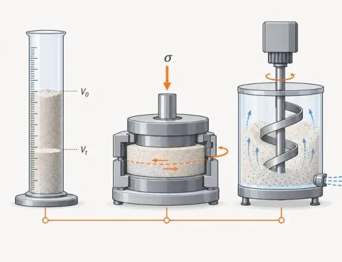
Choosing between dense-phase and dilute-phase conveying based on throughput and layout alone omits the information needed to predict attrition and segregation outcomes for a specific powder. A small set of test comparisons, run before and after a representative conveying trial or pilot loop, generally provides more decision-relevant evidence than a single generic index. Where dense-phase operation is under consideration, permeability and deaeration testing should be run first, since a negative result closes that option regardless of what the attrition data says.
Attrition Testing
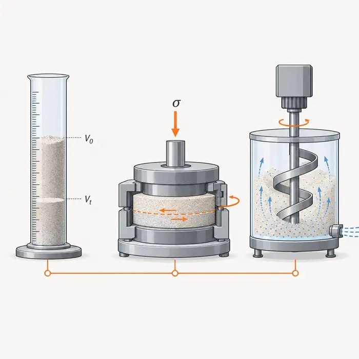
Standardized bench attrition indices, such as the jet cup approach in ASTM D8414/D8414M, were developed for fluid catalytic cracking catalysts and are not a direct substitute for testing a specific powder under its own conveying conditions. They illustrate what a controlled, repeatable attrition test looks like, and the same logic, applying a defined mechanical stress and measuring the resulting particle size change, can be adapted into a pilot-loop trial that mimics the velocity and loading ratio a plant intends to use.
For dilute-phase assessment specifically, controlled impact testing maps more directly onto the failure mechanism than a fluidized attrition index does. Accelerating particles to a defined velocity against a target at a defined impact angle reproduces what happens at a bend, and repeating the test across a velocity range establishes how steeply breakage scales with velocity for that material. A material whose breakage rises sharply across the range is one where velocity control, stepped-bore design, and bend count are the decisive variables. A material with a shallow response is one where the conveying mode matters less than the receiving-end design. A conveying trial that changes coating integrity or particle strength without yet showing up in particle size distribution is a common early-stage failure mode, discussed in Coated Particle Damage Before Particle Size Changes.
Particle Size Distribution Shifts
Comparing D10, D50, D90, and the fines fraction before and after a conveying trial is one of the most direct ways to detect attrition, provided the sampling captures material from both the leading and trailing portions of a dense-phase plug run, since particle size can vary along a plug run in ways that make a single grab sample unrepresentative. Guidance on reading these shifts in a process context, including what a narrowing or broadening distribution indicates about the underlying mechanism, is covered in Particle Size Distribution Interpretation. Research on whey protein isolate powder has shown that dilute-phase conveying can cause measurable particle breakage with knock-on effects on bulk powder properties, illustrating that PSD shifts from conveying are not limited to obviously fragile materials, as reported in a study of dilute-phase conveying and particle breakage in whey protein isolate powders.
Bulk Density and Tapped Density Changes
A shift in tapped or aerated bulk density after conveying is a supporting indicator that particle breakage or fines generation has occurred, since smaller fragments and additional fines typically pack differently than the original particle population. It is not, on its own, proof of a specific attrition mechanism, since bulk density is also sensitive to moisture pickup, deaeration state, and sampling handling. The value and the limits of bulk density as a single measurement are discussed in Bulk Density Alone Can Mislead Powder Analysis, and should be read alongside PSD and attrition data rather than in isolation.
Shear Cell and Flow Function Testing
Because attrition-generated fines usually increase cohesion, a shear cell measurement taken after a conveying trial can reveal a flow function change that would not be visible from particle size data alone, particularly for powders where the fines fraction is small but disproportionately active. The method and its interpretation are covered in Shear Cell Testing: The Key to Understanding and Controlling Powder Flow, and a comparison of flow test methods appropriate to different decision points is available in Selecting and Comparing Powder Flow Test Methods. A downstream flow function shift after conveying is a decision input for hopper and feeder design at the receiving end, not just a conveying-line metric.
Permeability and Deaeration Behavior
Dense-phase plug conveying depends on the powder retaining enough air permeability to allow plugs to form and move without excessive pressure buildup, and a shift toward a finer, more attrition-generated particle population can change that permeability behavior over a campaign. Fines content, deaeration rate, and conveying stability are linked, and the effect is discussed in Fine Powder Fluidization in Pneumatic Conveying and Discharge Control, relevant when attrition during a conveying run is gradually shifting the powder toward a more fluidizable, finer state than the one the system was originally designed around.
Building a Practical Decision Framework
A defensible conveying mode decision weighs the material’s demonstrated attrition sensitivity against the throughput, distance, and layout constraints that make dense-phase or dilute-phase practical in the first place. Bench or pilot attrition data indicating impact-dominated failure points first at velocity control through stepped-bore design and second at the bend arrangement itself. Bend count generally matters more than bend radius because each bend decelerates the particle stream and imposes a re-acceleration length downstream, adding both an impact event and a pressure-drop penalty.
Bend geometry is also less predictable than it is often assumed to be: long-radius bends are not reliably gentler than short-radius bends across materials, and blind tees, which trap a pocket of the conveyed material so that incoming particles strike their own kind rather than the pipe wall, trade wall erosion against particle damage in a way that depends on the powder. Bends generate ropes as well, dense strands of particles that persist for many pipe diameters downstream and concentrate both wear and attrition locally, which is a reason to keep diverter valves and instrument penetrations clear of the section immediately following a bend.
Data indicating compressive or shear-dominated failure points the other way, since dense-phase plug pressure may do more damage than a well-designed dilute-phase line. Segregation risk should be assessed separately for each mode, since dilute-phase segregation tends to appear downstream at the receiver while dense-phase segregation can develop within the plug itself during transport.