

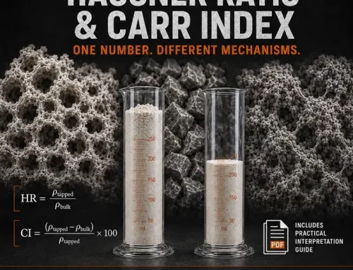
Why refills create a hidden process step
Most teams treat a refill as a simple top-up. In reality, a refill is a mechanical event that resets the stress history above the feeder.
Head height jumps. Local consolidation changes. Air gets introduced or trapped. In a continuous line, that becomes a repeatable inlet disturbance.
That is why the trend looks so familiar. The feeder runs steadily, refill happens, then mass flow bumps or sags in the same window every time. Operators blame the controller because the symptom appears in the control signal. The cause sits upstream, in the powder state at the inlet.
Refill-driven consolidation effects at the hopper to screw interface have been demonstrated experimentally in loss-in-weight feeding and can show up as a repeatable post-refill disturbance.
What actually changes at the screw inlet
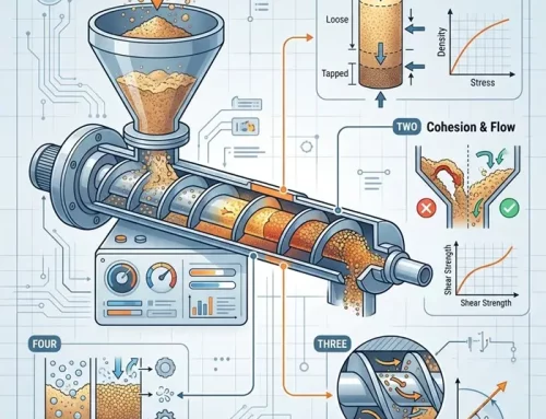
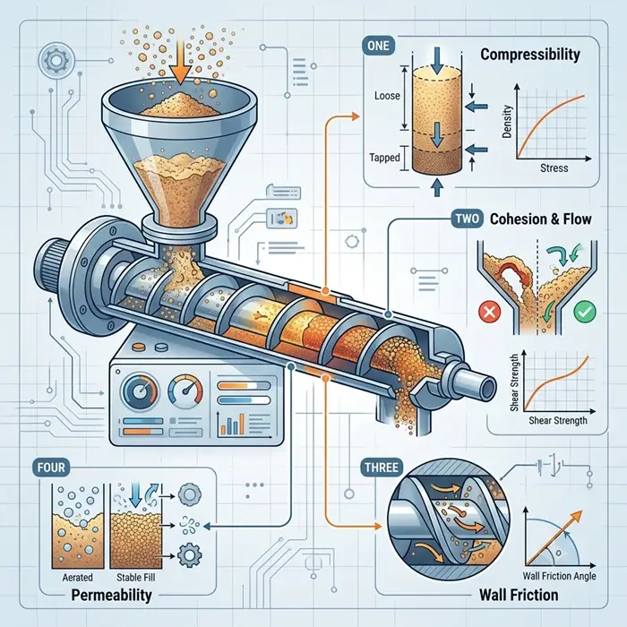
At the inlet, a screw meters a mixture of solids and air. The ratio drives screw fill, torque, and mass per revolution. Refill changes that ratio in two common ways.
Mechanism 1, densification step
After a refill, higher head height increases vertical stress. If the powder is compressible, the bulk density rises at the inlet. Contact number increases. The bed resists shear more strongly.
Permeability often drops at the same time. Air escapes more slowly during drawdown. The inlet becomes harder to deaerate, so torque rises and refill behavior becomes less repeatable.
You get a drift signature that looks like control lag, but it is a physical relaxation process. The bed is settling and venting.
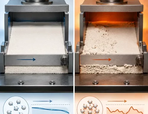
Mechanism 2, aeration step
Some refills introduce a loose layer with entrained air. Drop height, refill speed, and pneumatic transfer make this worse.
In that case, the screw acts like a compactor first. It compresses the inlet until the solids fraction increases enough to transmit load. During that compression, mass per revolution changes. The feeder can overshoot even if the screw speed stays constant.
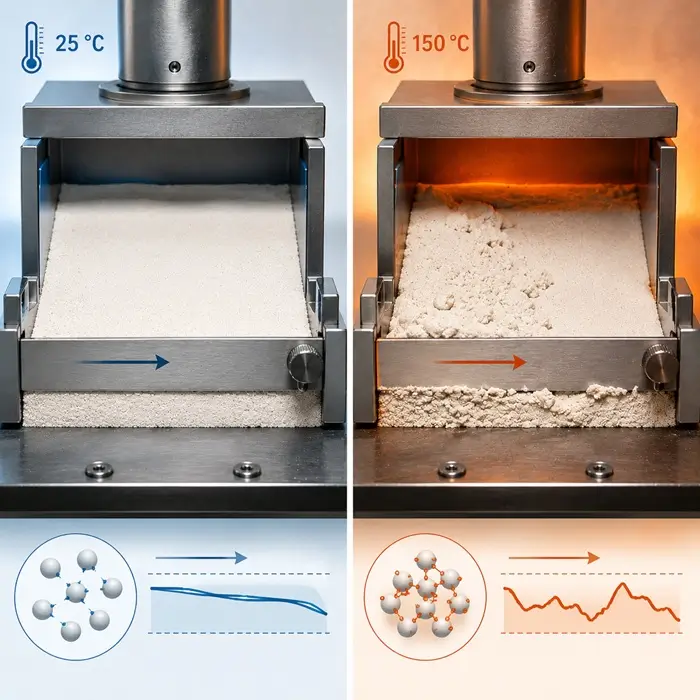
Both mechanisms can exist in the same system. Humidity and temperature then decide which one dominates on a given day.
The 10 minute proof using only line data
Before you touch PID settings, prove whether the disturbance is refill-driven.
Trend these on the same time axis:
-
mass flow rate
-
screw speed
-
motor current or torque
-
a refill marker, level switch, valve open, or manual timestamp
Now check the timing. If the disturbance starts right after refill and repeats consistently, you are seeing an inlet state step. Control tuning cannot remove the step. It can only soften the response.
Use the shape of the response to separate the mechanisms:
-
Current steps up after refill and recovers slowly suggests densification plus slow deaeration.
-
Mass overshoots with a smaller torque change suggest aeration and transient compaction at the inlet.
-
Response time changes with moisture suggests permeability and cohesion are coupling into the refill event.
Minimal bench work that adds real information
You do not need a full test campaign to act intelligently. You need one curve that matches the stress range at the feeder inlet.
-
Run a compressibility curve: bulk density versus applied stress.
-
Estimate the consolidation stress range above the screw at low and high levels.
-
See whether a refill produces a meaningful density step in that stress range.
If you need to quantify how density translates into resistance, add a small set of shear points around that same consolidation window. That gives you a defensible link between packing state and yield strength. For a defensible shear method and terminology, use ASTM D6128 (shear testing for bulk solids).
If your drift comes with dust puffs, flooding, or surging, add a simple permeability or deaeration sensitivity check. Low permeability turns a small density change into a large operating change.
What to change so the inlet state stops moving
Once you confirm refill-driven drift, the goal is stable inlet conditions. Start with the levers that reduce the size of the refill step.
Reduce refill amplitude
Smaller, more frequent refills reduce the jump in head height. This often cuts drift immediately.
Control aeration during refill
Reduce drop height. Avoid plunging the stream into the bed. If pneumatic fill is unavoidable, improve venting where air must leave.
Fix the geometry that stores stress history
Tight pockets, dead volumes, or sliding surfaces above the screw can create local overconsolidation. That material is later released as a denser plug. The trend then looks like controller instability.
Vent where air has no escape path
Transitions above the screw often trap air. If air cannot leave, the inlet state stays unstable longer.
Use agitation carefully
Some devices deaerate, others compact. Watch the torque response after refill. If torque increases and recovery slows, your agitation is adding consolidation.
A practical decision rule you can hand to operations
If mass flow deviation begins within minutes after refill, and torque change aligns with refill events, treat it as a refill shock problem.
Then do this in order:
-
Reduce refill amplitude and drop height.
-
Improve venting and remove sealed pockets.
-
Only then revisit tuning.
That order prevents weeks of tuning work that only masks the symptom.


