
Table of Contents

In this article, we will delve into Pneumatic Conveying Wear of Materials. pneumatic conveying typically moves materials from a single source, such as a silo or hopper, to one or more destinations over relatively long distances. During this process, particles travel on a high-velocity airstream throughout the system. They interact with the pneumatic transport system, which consists of pipelines with many twists and turns.
As a result of this interaction, the impact of the material can lead to wear on the conveying pipeline. To assess pneumatic conveying wear, we first examine the air velocity, the number of bends, and the angle of those bends. Additionally, we consider the brittleness or hardness of the material. Together, these aspects are critical parameters for determining the potential wear on the transported material.
Pneumatic Conveying Wear of material
Particle wear can easily occur during the material conveying process, creating several potential hazards. Airborne fine particles released as a result of wear can enter the atmosphere, posing health risks and potential explosion hazards.
Additionally, issues related to production quality may arise during transport. Pneumatic transport wear can affect the applied coating of materials or alter the particle size and shape. These changes can directly influence product quality and production consistency.
The most common causes of wear during transportation stem from particle-to-particle impacts and particle-to-wall impacts. These interactions frequently occur in bends and transition areas within the conveying lines.
One typical case of wear that significantly impacts product quality is the handling of milk powder. During the conveying process, the powdered milk can break at the bends. This breakage may alter the particle size distribution, leading to several process issues, including packaging challenges, caking, and dissolution problems.

Figure 1: Particle size distribution result of milk powder under different air velocities by pneumatic conveying.

Figure 2 shows the particle size distribution results after applying different air velocities in the pneumatic conveying system. The red line is the original particle size of the material. After applying the different velocities, the particle sizes decreased to a certain extent.

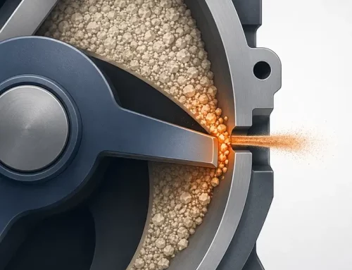
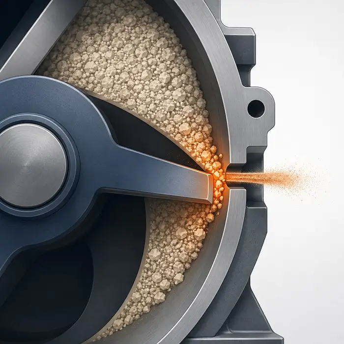
Figure 3: Particle breakage of bio-granules (center) by different bend types in the pneumatic conveying system evidencing clearly more fines in the radius bend (right) compared to the mitered bend (left).

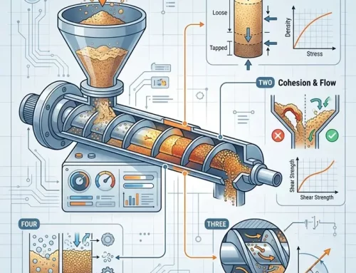
Figure 4: Schematic representation of CS-RIT and the mechanical mechanisms of CS-RIT.
Pneumatic Conveying Wear -Mitigating Dust Generation Risks in Bio-Granule Conveying
Another relevant case to examine is that of bio-granule products. These products are known for their brittleness, making them susceptible to generating dust particles during the conveying process. As bio-granules move through the pneumatic system, the mechanical forces at play can cause them to break apart, leading to an increase in fine particles.
Our analysis revealed that different bend types, especially those with varying radii, significantly impacted particle generation. Tighter bends tend to produce more dust, while gentler curves can reduce the likelihood of particle breakage. However, even with gentle bends, the potential for dust generation remains a concern.
This increase in fine particles poses a higher risk of explosion hazards, particularly in environments where dust can accumulate. These risks are regulated under ATEX (Atmosphères Explosibles), which outlines safety requirements for equipment and protective systems used in explosive atmospheres. Compliance with ATEX regulations is crucial to ensure the safety of both personnel and facilities.
To mitigate these risks, it’s essential for manufacturers to assess their pneumatic conveying systems carefully. This includes evaluating the design of the conveying system, selecting appropriate bend types, and implementing measures to control dust generation. By doing so, companies can enhance product quality and ensure compliance with safety regulations, ultimately leading to a safer and more efficient production process.
How laboratory insights meet the practice of the industrial process
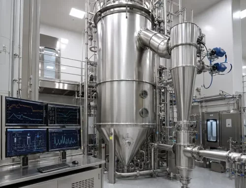
At Delft Solids Solutions, we can explore these situations and others because we can mimic industrial conveying on a lab scale to quantitatively predict the wear of powder and granule particles. Our lab-scale pneumatic conveying system features a total pipeline length of 2 meters. This setup allows us to apply a varying number of bends and bend types, switching between 3, 6, and 9 bends.
We offer two different types of bends: different radius bends and mitered bends. This flexibility enables us to simulate various conveying scenarios and their impacts on particle wear. During the conveying process, we can apply different air pressures throughout the system, allowing us to achieve particle velocities of up to 20 m/s.
By replicating real-world conditions, we gain valuable insights into how different configurations affect wear and dust generation. This capability not only helps us understand the implications of pneumatic conveying on product quality but also informs strategies to mitigate wear and enhance safety. Through these experiments, we provide clients with precise data and recommendations tailored to their specific materials and processes, ultimately improving operational efficiency and product integrity.
Delft Solids Solutions also offers repeated impact test
The repeated impact test is a technology developed to simulate wall impacts through controlled, constant velocity collisions. In this test, a vertical particle box moves to ensure that the particles collide with the wall, effectively mimicking the impact experienced in the bends of a pneumatic conveying system, as illustrated in Figure 3.
This repeated impact tester offers several advantages. One of the most significant benefits is that it requires only small amounts of sample material for testing. Typically, between 1 and 2 grams of material are sufficient for the test. This feature is particularly beneficial for companies that may struggle to provide larger quantities of sample material, such as those in the pharmaceutical industry, where materials can be costly and scarce.
By minimizing the sample size needed, the repeated impact test enables a wider range of industries to evaluate their materials without incurring significant costs or resource constraints. This technology allows companies to gain critical insights into the wear characteristics of their products, ultimately helping them improve product quality and reduce risks associated with pneumatic conveying.
How laboratory insights meet the practice of the industrial process
At Delft Solids Solutions, we can explore various scenarios by mimicking industrial conveying on a lab scale. This allows us to quantitatively predict the wear of powder and granule particles. Our lab-scale pneumatic conveying system features a total pipeline length of 2 meters. We can apply a varying number of bends and bend types, switching between 3, 6, and 9 bends, and utilizing two different bend types: different radius bends and mitered bends. Throughout the conveying process, we apply different air pressures in the system to achieve particle velocities of up to 20 m/s.
In addition to our pneumatic conveying system, Delft Solids Solutions also offers a repeated impact test. This technology is designed to simulate wall impacts through controlled, constant velocity collisions. The vertical movement of the particle box ensures that particles collide with the wall, effectively mimicking the bend impacts experienced in pneumatic conveying systems, as shown in Figure 3.
The repeated impact tester has several advantages. It requires only small amounts of sample material—typically between 1 and 2 grams. This is particularly suitable for companies that may struggle to provide larger quantities of sample material, such as those in the pharmaceutical industry, where materials can be costly and limited in availability. By minimizing the sample size needed for testing, we enable a broader range of industries to assess their materials, gain valuable insights into wear characteristics, and ultimately improve product quality and safety.
Impact Extrapolation
Due to the high frequency of the repeated impact test, it can easily reach thousands of collisions, equating to hundreds of bend simulations in the pneumatic conveying system. This makes the repeated impact test highly suitable for clients looking to explore the effects of maximum collisions within their production processes.
The correlation between pneumatic conveying and repeated impact test results can be quantified using kinetic energy. The kinetic energy transfer table versus mass fraction, as illustrated in Figure 4, indicates that particle wear during pneumatic conveying shows a strong correlation with results from the repeated impact test.
As we increase the kinetic energy in both systems, the mass fraction results appear similar from 3 m/s to 9 m/s. This consistency suggests that the repeated impact test effectively simulates extreme conveying conditions. By leveraging this technology, Delft Solids Solutions can simulate situations involving thousands of collisions, providing valuable insights into particle wear and helping clients optimize their processes for better product quality and safety.


