Updated: November 7, 2026
Table of contents

An incoming powder meets its specification. Will it still meet that specification after the drum has been opened, the material has passed through a feeder, and the last portion has reached the mixer? For a battery manufacturer, the answer may depend on a single wear fragment or on how long a sulfide electrolyte spent in the transfer enclosure. Battery materials illustrate five handling risks that also arise with other functional powders, where a small change in chemistry, particle condition, or dose can affect the finished product.
1. Contamination: Find the particle that can cause the defect
A metallic fragment in battery production can damage a separator and create a path for an internal short circuit. Its dimensions, shape, and location matter. The same mass of metal distributed as trace impurities poses a different diagnostic question. Equipment wear and cutting debris are among the potential sources. Battery defect study by Bergmann and colleagues
Suppose a feeder starts shedding metal. A bulk elemental assay such as ICP-MS after digestion can quantify the metal in the test portion, but digestion destroys the evidence that it was present as a fragment. A sample that misses the fragment can still meet the elemental specification. If discrete debris is the concern, compare representative samples from before and after the suspected wear point. Magnetic collection can recover susceptible steel debris.
To recover copper or aluminum, first establish a preparation that separates the powder matrix while preserving the target fragments. Depending on the matrix and size range, collect the residue on a membrane or use a wet sieve to retain coarse fragments. A filter alone will also collect undissolved powder of comparable size. Automated optical microscopy can count and size the recovered particles. Use scanning electron microscopy with energy-dispersive X-ray spectroscopy (SEM-EDX) to identify the elements in suspect fragments. Check recovery with known fragments of the relevant metals and sizes, including any losses during sample preparation.
Define acceptance in terms of the defect the product can tolerate. An elemental concentration limit and a limit on the number and size of foreign particles may both be necessary. Verify recovery and sampling sensitivity before interpreting a clean result. Where the source is a product-contact surface, inspect that surface and validate the cleaning method against the residue and the powder’s chemical compatibility.
2. Moisture and oxygen: Qualify the whole exposure
For sulfide solid electrolytes, moisture exposure can release hydrogen sulfide (H₂S) and reduce ionic conductivity. The two responses can differ enough to change a batch decision. Yersak and colleagues exposed five related sulfide glass powders to a dry room at a −40 °C dew point for 30 minutes. Ionic conductivity fell by approximately 52% to 77%, depending on composition. One oxide-modified glass released very little detectable H₂S, yet its conductivity fell from 0.31 to 0.15 mS/cm. A low gas reading would have missed that loss of function. Conductivity and gas-release measurements, Table 1
A separate study found that Li₆PS₅Cl, an argyrodite electrolyte, lost 36% of its ionic conductivity over three days at a dry-room dew point of −60 to −70 °C. The different material and exposure duration prevent a direct comparison of the two dew points. They do show why a room specification alone is insufficient to release an exposed batch. Dry-room exposure study of Li₆PS₅Cl
Start with the supplier’s handling specification. Record the conditions where the powder is actually exposed and the cumulative time spent opening, transferring, sampling, and waiting. Include a credible production delay in qualification. For a sulfide electrolyte, compare the conductivity of exposed and sealed material. Where oxidation is a concern, measure oxygen separately and verify the relevant product property. A dew-point sensor measures moisture. Oxygen monitoring and toxic-gas detection serve different purposes and require their own acceptance or response criteria.
3. Flowability: Match the test to the discharge problem
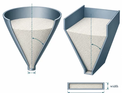
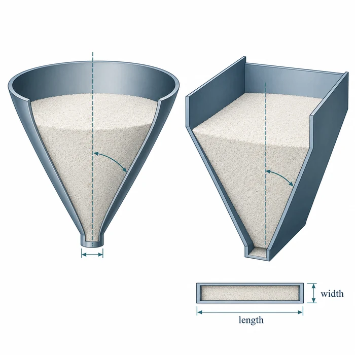
Consider a cohesive cathode precursor that feeds steadily until the line stops, then arches on restart. A hopper can have walls steep enough for powder to move along them and still stop discharging when a cohesive arch forms across the outlet. Wall angle and outlet size answer different design questions. Wall-friction tests against the intended contact surface help determine the wall angle required for mass flow, in which the whole bed moves during discharge. Cohesive-strength measurements under representative consolidation conditions help determine the outlet size needed to prevent arching. ASTM D6128 describes measurements with the Jenike shear tester. Include storage time if interruptions leave the powder at rest before restart. ASTM D6128
A sudden surge points to a different mechanism. Fine powder can retain gas after filling or pneumatic transfer and discharge before the bed has deaerated. If a feeder alternates between starvation and flooding, document the sequence of filling, settling, and discharge before adding aeration. Evaluate the proposed gas for compatibility with the powder and check the resulting dose variability under actual operating conditions. Guide to powder flooding and flushing
A flow aid such as fumed silica changes the formulation. If the product specification permits it, assess dosing repeatability, charging during transfer, and the finished material’s performance at the proposed addition level.
4. Electrostatic charging and combustible dust: Assess the transfer
Charging during transfer
A grounded metal hopper can receive powder that acquired charge while moving through a transfer line. Bonding and grounding give conductive equipment a path to dissipate charge. An electrically insulating powder may retain charge after it enters the hopper. To assess the transfer, consider the powder, the surfaces it contacts, the continuity of conductive components, and how quickly charge decays under the operating atmosphere. A change of hose or liner can alter the assessment even when the powder formulation stays the same.
Ignition sensitivity and explosion severity
Where a combustible dust cloud can form, separate ignition sensitivity from explosion severity. ASTM E2019 measures the minimum ignition energy of a dust cloud in air under defined conditions. ASTM E1226 characterizes dust-cloud explosibility and, for an explosible sample, provides severity data including maximum explosion pressure and the deflagration index, KSt. For reactive or air-sensitive powders, give the testing laboratory the material hazards, process atmosphere, and condition of the dust likely to accumulate, including fines. Have a qualified specialist establish appropriate methods and interpret their applicability to the process. ASTM E2019 · ASTM E1226
Requirements for the installation
For a US battery line, first establish whether the powder as handled presents a combustible-dust hazard and which requirements apply to the facility. Where applicable, use the NFPA 660 dust hazard analysis to identify where a cloud could form, where ignition is credible, and which safeguards the operation needs. Before using NFPA 77 to select static controls, check the room designation. A dry room controls moisture and may also be a classified cleanroom. If it is, the cleanroom exclusion in NFPA 77 (2024), §1.1.7 applies. Have the facility’s fire-protection specialist establish the basis for static control in that room. Low dew point alone does not trigger the exclusion.
For an EU installation, start with the employer’s assessment under ATEX Directive 1999/92/EC. Identify where an explosive atmosphere can arise and classify hazardous places as required. Use that assessment when specifying equipment within the scope of ATEX Directive 2014/34/EU. In Great Britain, the same practical distinction guides the work: assess workplace risks under DSEAR, then check the suitability and conformity of equipment supplied for the identified location under the 2016 EPS Regulations. HSE explains the workplace and equipment duties.
5. Equipment materials: Check wear, cleaning, and return to service
For an abrasive oxide, a harder contact surface may reduce metal pickup, but a chipped ceramic coating introduces a different contaminant. When qualifying an elbow, feeder screw, or valve, identify what can wear into the product and how the damage will be detected. Pair inspection of the component with downstream powder samples. If the proposed coating changes the hopper’s contact surface, include it in wall-friction testing as well.
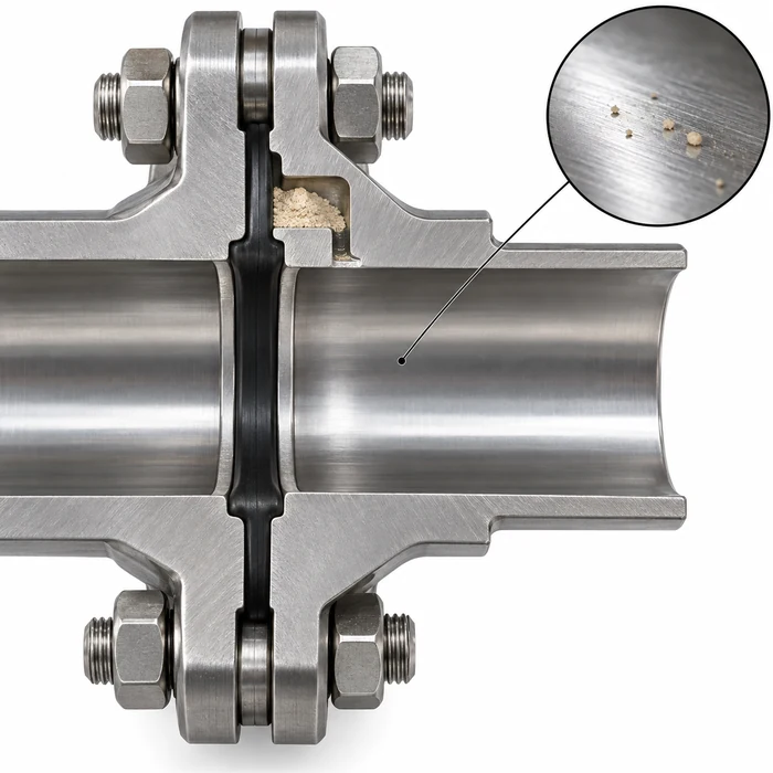
Cleaning may expose a component to chemistry it never encounters during dry transfer. On lines that also handle lithium hexafluorophosphate (LiPF₆) electrolyte salt, water introduced during cleaning can react with residual salt to form hydrogen fluoride (HF). Assess that reaction before authorizing a wet cleaning step. Check contact surfaces and seals for compatibility with the chemical species, concentration, and temperature expected during operation, shutdown, and cleaning. Include any wet residues or condensation, and use the manufacturer’s compatibility data for the exact elastomer compound and cleaning medium.
Before returning the line to service, verify the conditions that matter at the next powder contact. For a moisture-sensitive electrolyte, that includes dryness at the transfer point. For a powder with a tight foreign-particle specification, it includes the condition of the wear surfaces and the ability of the sampling method to recover the debris of concern.