Article revised and updated on November 6 2026
- Key takeaway
- Why Powder Becomes Charged
- Recognize the Symptoms, Then Test the Cause
- Measure Charge Generation and Retention
- Use MIE to Identify Decisions That Need More Attention
- Select and Verify the Controls
- Confirm Performance Under Plant Conditions
- Frequently Asked Questions
- Technical Basis / Sources
- Related Reading
- About the Author: Stephane Sloots
- Related Posts

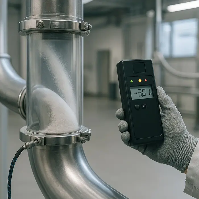
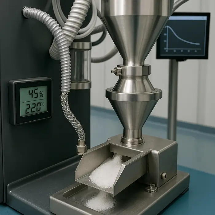
A feeder becomes erratic during dry weather. Powder starts coating a chute after a hose replacement. Electrostatic charging can explain these changes, but the symptoms alone do not establish the cause. Locate the charging step, measure what reaches the next operation, and check whether reducing charge improves performance.
If combustible dust or flammable gas or vapor can be present, assess electrostatic ignition hazards before changing the equipment or operating conditions. A measure that improves flow does not, by itself, establish ignition safety.
Why Powder Becomes Charged
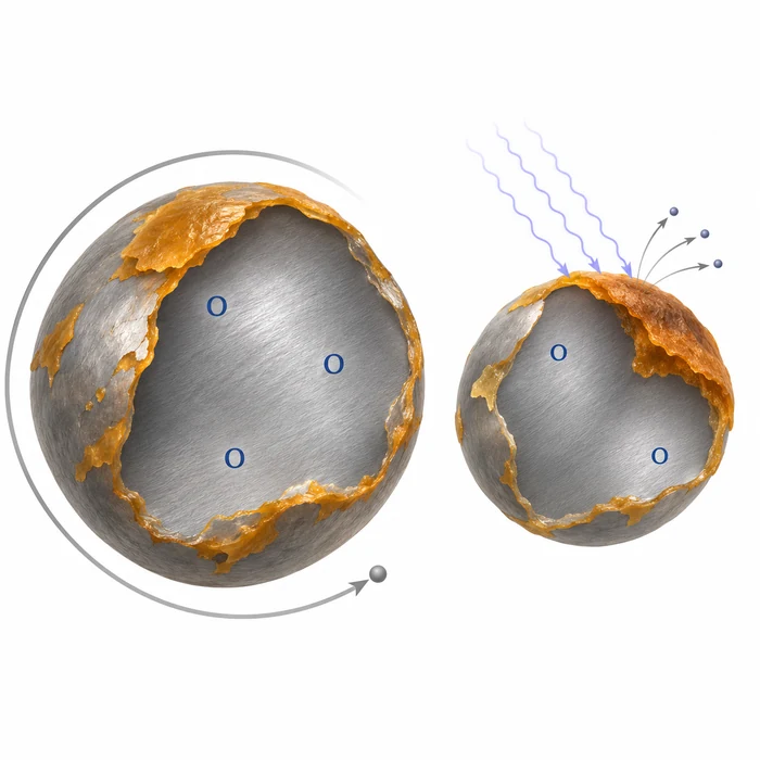
Particles exchange charge when they contact and separate from equipment surfaces or other particles. This contact charging, often called triboelectric charging, occurs during conveying, mixing, sieving, feeding, and filling. Charge magnitude and polarity depend on the contacting materials, surface condition, moisture, and handling history.
Pneumatic conveying creates repeated particle-wall contacts. In a PMMA duct study, Xu and Grosshans found that the charge leaving the system varied with atmospheric moisture. Charge initially increased with absolute humidity before falling at higher values [1].
Charge generation and charge retention are separate questions. Grounded metal provides a discharge path for the equipment. An insulating powder can retain charge inside it, while a metal fitting isolated by a gasket or plastic hose can become a charged conductor.
PTI’s Triboelectric Charging in Powders explains the contact mechanisms in more detail.
Recognize the Symptoms, Then Test the Cause
Investigate electrostatics when you observe:
- Powder adhering to walls, windows, or packaging.
- Erratic feeding or incomplete discharge.
- Unexpected agglomeration or changes in blend uniformity.
- Shocks experienced by operators.
- Visible or audible discharges.
Also check competing explanations. Moisture, deposits, surface damage, and mechanical faults can produce similar symptoms.
Start with what changed. Record hose and liner replacements, cleaning agents, powder moisture, seasonal conditions, and operating settings. Then compare charge measurements with a relevant process outcome, such as deposited mass or feed-rate variation.
Measure Charge Generation and Retention
Charge-to-Mass Ratio: What Leaves the Operation?
A Faraday cup measures the net charge collected with a sample. Divide that charge by sample mass to obtain the charge-to-mass ratio, usually expressed in µC/kg.
Collect samples immediately after the suspected charging step using consistent timing and handling. Record polarity as well as magnitude. Positive and negative particle populations can cancel in the net reading, while a sampling delay can allow charge to dissipate.
IEC TS 60079-32-1, Table A.1, gives the following measured ranges for medium-resistivity powders emerging from different operations. Carluccio and Perelli reproduce the table in their electrostatic risk-assessment paper [2].
| Operation | Reported charge-to-mass magnitude, µC/kg |
|---|---|
| Sieving | 0.00001–0.001 |
| Pouring | 0.001–1 |
| Grinding | 0.1–1 |
| Pneumatic conveying | 0.1–1,000 |
These are reference ranges, not acceptance limits. They show how widely charging varies between operations. They do not predict the result for a particular powder or establish whether a measured charge is safe.
Bulk Resistivity: Can Charge Reach Ground?
Measure bulk volume resistivity in Ω·m under specified moisture, temperature, and packing conditions. The IEC powder classification uses these bands [2, 3]:
| Powder classification | Bulk volume resistivity, ρ | Practical interpretation |
|---|---|---|
| Low resistivity | ρ ≤ 10⁶ Ω·m | Charge can dissipate readily through a connected powder bed when it has effective contact with ground. |
| Medium resistivity | 10⁶ < ρ ≤ 10¹⁰ Ω·m | Establish whether dissipation is fast enough for the handling sequence. |
| High resistivity | ρ > 10¹⁰ Ω·m | Persistent charge in the powder bed becomes a stronger concern. |
The bands describe bulk material. They do not establish how rapidly airborne particles discharge, because the surrounding air interrupts the conductive pathway.
Charge Decay: How Long Does Charge Persist?
Ask the laboratory for a charge-decay curve, including the charging method, sample arrangement, grounding condition, humidity, and reported decay endpoint.
IEC 61340-2-1:2015+AMD1:2022 describes corona-charging and charged-metal-plate methods. Corona charge decay evaluates dissipation from a material’s own surface; the plate method evaluates dissipation from a conductive object contacting the material. The methods are not interchangeable [4]. For powder, agree on a suitable sample holder and preparation procedure with the laboratory.
Relate the result to the process. A powder that retains substantial charge for several minutes can carry it through a short transfer into the next operation. Surface charge-decay testing should therefore be considered alongside measurements after representative handling.
Use MIE to Identify Decisions That Need More Attention
Minimum ignition energy, or MIE, describes the ignition sensitivity of a tested dust cloud. Use results for the relevant fine fraction and moisture condition, and obtain the test circuit details. For electrostatic assessment, results without added inductance are particularly relevant [3].
| MIE decision point | What changes in practice |
|---|---|
| Below about 10 mJ | Personnel charging becomes a prominent ignition concern. Verify the operator’s complete path to ground. |
| At or below 3 mJ | FIBC selection tightens: Type B is outside its dust-MIE use range. Assess Type C or D with the surrounding atmosphere and liner. |
| Below 1 mJ | Investigate whether evolved gas or vapor contributes to the result, and assess the resulting atmosphere explicitly. |
These points concern different mechanisms. A result above 10 mJ does not remove risks from isolated conductors, cone discharges, or propagating brush discharges. Likewise, ordinary brush discharges should not be confused with propagating brush discharges: their ignition capabilities differ [3, 5, 6].
Select and Verify the Controls
Ground and Bond Conductive Equipment
Bonding connects conductive items electrically. Grounding connects them to earth.
For ordinary metallic equipment, IEC TS 60079-32-1, Clause 13.2.2, provides two useful practical criteria:
- Below 10 Ω: the expected resistance for metallic items in good contact with earth.
- Up to 1 MΩ: generally acceptable for static dissipation, although a reading above 10 Ω on a metallic path warrants investigation.
The lower figure is a connection-integrity benchmark; the higher figure concerns static dissipation. Apply equipment-specific criteria where they differ.
Check removable fittings, clamps, portable containers, and components separated by gaskets. Paint, corrosion, and powder deposits can interrupt continuity. Establish the connection before transfer and maintain it throughout the operation.
Include Personnel in the Grounding System
A charged person can discharge to grounded equipment. Use dissipative footwear with a suitable floor, and verify the complete person-to-earth system. “Antistatic footwear” on its own does not establish that the installed combination works.
A commonly applied IEC criterion is less than 100 MΩ from the person to earth [5]. At stationary filling stations, an assessed wrist-strap system can provide an additional route, provided electrical and entanglement hazards are addressed.
Choose the FIBC and Liner Together
IEC 61340-4-4:2018 covers electrostatic classification and testing of flexible intermediate bulk containers, including inner liners [6].
| FIBC type | Electrostatic function | Main limitation |
|---|---|---|
| A | No specific static protection | Unsuitable where electrostatic protection is required. |
| B | Low-breakdown-voltage fabric limits propagating brush discharges | Does not dissipate charge; unsuitable for flammable gas or vapor atmospheres and dust MIE ≤3 mJ. |
| C | Conductive construction carries charge to ground | Requires a reliable ground throughout filling and emptying. |
| D | Static-protective construction operates without grounding the bag | Must be used within its qualified conditions; surrounding conductors still require grounding. |
Select the bag–liner combination, powder, and surrounding atmosphere together. A separately purchased liner can invalidate the intended protection.
The 2018 standard increased the Type C bag resistance-to-ground limit to 100 MΩ. This is a bag performance criterion, not a replacement for checking the metallic grounding connection.
Control Humidity Within the Powder’s Operating Range
There is no humidity at which all powders stop charging.
Schella and colleagues found material-dependent transitions in shaken polymer granulates. Some hydrophobic materials retained measurable charge even above 80% relative humidity [7]. The PMMA duct study also showed that increasing atmospheric moisture initially increased charging [1].
Test humidity changes against charge, flow, and product quality. More moisture can increase cohesion and caking through liquid bridges [8]. Record temperature and allow sufficient conditioning time before comparing results.
Verify Hoses and Coatings as Assemblies
A conductive hose is effective only when its conductive parts and fittings have the intended electrical connections. Assess the inner surface, wall construction, fittings, and grounding arrangement together.
A bonded metal helix does not establish that the inner hose surface dissipates charge. Similarly, an insulating coating on grounded metal needs assessment for propagating brush discharge risk. Select the construction for the actual powder, charging conditions, and atmosphere [3].
Test Additives in the Actual Formulation
A flow aid can improve handling while changing electrostatic charge in an unfavorable direction.
Ramirez-Dorronsoro and colleagues measured substantial differences among pharmaceutical powders contacting stainless steel. Colloidal silicon dioxide produced the strongest negative chargeability in their apparatus [9].
That result does not predict every blend. Compare untreated and treated formulations at the intended concentration, measuring both charge and the handling property you want to improve.
Keep Ionization Within Its Reach
Ionizers treat accessible surfaces and exposed powder streams. They do not neutralize charge throughout a bulk heap or silo.
Their performance depends on distance, exposure, airflow, cleanliness, and charging rate. Verify the result at operating throughput, and use equipment suitable for the hazardous area where applicable. Ionization supplements grounding and process design [3].
Confirm Performance Under Plant Conditions
Choose a measurable outcome before the trial: steadier feeding, less deposition, improved discharge, or another defined process result. Then change one controllable factor and repeat the comparison.
Cover the conditions that challenge the control, including dry weather, throughput changes, and normal component wear. Record the operating range and inspection requirements so operators can recognize when the control has deteriorated.
For a systematic investigation, see PTI’s Electrostatic Troubleshooting in Powder Handling.
For ignition assessment, use IEC TS 60079-32-1 alongside the applicable regional framework. Relevant US documents include NFPA 77:2024 and NFPA 660:2025. In the EU, the ATEX workplace and equipment directives apply; Great Britain uses DSEAR and the EPS Regulations [3, 10–12].
Frequently Asked Questions
Technical Basis / Sources
- 1. Xu, W., and Grosshans, H. (2023). Experimental study of humidity influence on triboelectric charging of particle-laden duct flows. Journal of Loss Prevention in the Process Industries, 81, 104970.
- 2. Carluccio, L. M., and Perelli, S. (2023). Electrostatic Risk Assessment for Combustible Dust Atmospheres. Chemical Engineering Transactions, 104, 61–66.
- 3. International Electrotechnical Commission. IEC TS 60079-32-1:2013+AMD1:2017: Explosive atmospheres, Part 32-1: Electrostatic hazards, guidance.
- 4. International Electrotechnical Commission. IEC 61340-2-1:2015+AMD1:2022: Measurement methods, ability of materials and products to dissipate static electric charge.
- 5. Smallwood, J. (2015). 60079-32-1: The new standard on avoidance of electrostatic hazards. Hazards 25, Symposium Series No. 160.
- 6. International Electrotechnical Commission. IEC 61340-4-4:2018: Electrostatic classification of flexible intermediate bulk containers.
- 7. Schella, A., Herminghaus, S., and Schröter, M. (2017). Influence of humidity on tribo-electric charging and segregation in shaken granular media. Soft Matter, 13, 394–401.
- 8. Zafar, U., Vivacqua, V., Calvert, G., Ghadiri, M., and Cleaver, J. A. S. (2017). A Review of Bulk Powder Caking. Powder Technology, 313, 389–401.
- 9. Ramirez-Dorronsoro, J. C., Jacko, R. B., and Kildsig, D. O. (2006). Chargeability measurements of selected pharmaceutical dry powders to assess their electrostatic charge control capabilities. AAPS PharmSciTech, 7, article 103.
- 10. National Fire Protection Association. NFPA 77: Recommended Practice on Static Electricity. 2024 edition.
- 11. National Fire Protection Association. NFPA 660: Standard for Combustible Dusts and Particulate Solids. 2025 edition.
- 12. Health and Safety Executive. ATEX and explosive atmospheres.