

Sieve blinding often looks like a maintenance problem. Production sees a capacity drop, operators clean the mesh, and the line starts again. Sometimes that works. Often, the same problem returns because the root cause sits in the powder behavior.
A sieve is not only a size separator. It is also a contact surface, a vibration zone, a classifier, and sometimes a weak agglomerate breaker. Particles interact with the mesh, with each other, and with air inside the powder bed. That means screening connects directly to broader powder handling and processing decisions.
That interaction matters. A screen can pass a commissioning test and still fail during normal production. The particle size analysis may look acceptable on paper, while the mesh slowly loses open area during operation.
Why Sieve Blinding Changes the Material Stream
Once sieve blinding develops, the screen no longer protects the downstream process in the way the specification assumes. It starts editing the material stream.
That matters because screening is often treated as a simple safeguard. Material above the cut point stays behind, and material below the cut point passes forward. In real production, that assumption only holds while the mesh remains open enough for particles to reach and pass through the apertures.
When the open area drops, the screen applies a different separation than expected. It may retain useful material, pass an uneven fine fraction, or create batch variation before the next process step begins. Downstream teams may then blame the hopper, feeder, mixer, or classifier, while the first shift happened at the screen.
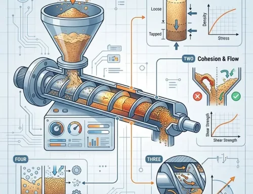
The Four Main Mechanisms Behind Sieve Blinding
Most sieve blinding problems come from one or more of four mechanisms: wedging, coating, agglomeration, or overload.
Near-size wedging occurs when particles sit close to the aperture size. They are small enough to enter the opening, yet too large, angular, elongated, or irregular to pass through cleanly. These particles lock into the mesh and reduce the open area.
Fine-particle coating happens when small particles cling to the wire surface. This often involves moisture, electrostatic charge, fat, binder residue, or high surface area fines. The mesh then behaves less like a classifier and more like a surface collecting a thin powder layer. In these cases, powder stickiness measurement may be more relevant than another particle size check.
Agglomeration creates another route to poor separation. Some powders reach the sieve as loose clusters. Others form clusters during vibration because repeated contact, humidity, charge, or surface stickiness pulls particles together. These agglomeration effects can make fine material behave like oversized material, even when the primary particles should pass.
Bed overload occurs when too much powder sits on the screen. Fine particles cannot reach the apertures efficiently because a moving layer of material blocks access to the mesh. The screen may still look active, while the separation quality drops.
Why the Particle Size Report Can Mislead You
A particle size report describes the sample under the test conditions used. It does not automatically predict how the same powder will behave on a vibrating screen, rotary sieve, check sieve, or inline classifier.
A powder with a narrow particle size distribution can still blind a screen if many particles sit near the aperture size. A powder with a broad distribution may screen well if the fractions are clearly separated. Fines content also needs context. A modest amount of fines can create serious blinding when those fines carry charge, absorb moisture, or coat the mesh.
Standards such as ASTM E11 and ISO 3310-1 help define sieve cloth, aperture requirements, and test sieve construction. They do not remove the need to understand how the powder behaves during real screening.
Particle shape adds another variable. Spherical particles pass through openings more predictably than elongated, flaky, or angular particles. An irregular particle can bridge an aperture in one orientation and pass in another.
Therefore, sieve blinding gives useful diagnostic information. It shows that the problem is not only dimensional. Adhesion, cohesion, moisture, charge, shape, feed rate, and handling history may all play a role.
How to Diagnose Sieve Blinding Before Changing the Mesh
Start with the blinded screen itself. The pattern usually tells you where to look first.
If individual apertures are blocked, check for near-size particles and irregular particle shape. The screen may be operating too close to the real particle size distribution.
If the mesh has a fine film or coated appearance, look at fines, moisture, electrostatic charge, and surface chemistry. More vibration may clear the screen temporarily, but the powder will often coat the mesh again.
If soft lumps sit on top of the screen, check whether agglomerates entered the sieve or formed during screening. Review humidity history, storage conditions, vibration intensity, and upstream handling.
If the bed looks deep, uneven, or slow-moving, check feed rate and distribution. A screen cannot classify properly when the powder arrives as a dense ribbon, a pulsing slug, or an overloaded layer. These conditions may also affect powder flowability downstream.
This diagnostic order avoids a common mistake. Plants often respond to sieve blinding by increasing vibration, changing mesh, or adding cleaning devices. Those changes may help, but they do not fix the wrong cut point, a moisture problem, static buildup, or poor feed presentation.
The Practical Decision Rule for Sieve Blinding
Use the blinding pattern as the first decision point.
Blocked openings point toward near-size wedging, particle shape, or an aperture that sits too close to the bulk of the distribution.
A coated mesh points toward fines, moisture, charge, or sticky surface chemistry.
Soft lumps point toward agglomeration, storage history, vibration effects, or upstream handling.
A moving powder layer that never exposes enough mesh points toward overload, feed distribution, or residence time.
This approach changes the question. Instead of asking whether the screen is good enough, ask why the powder reduces open area under real operating conditions.
That shift usually leads to better process decisions. Sometimes the answer is a different aperture. Sometimes it is staged screening, improved feed distribution, tighter moisture control, antistatic measures, or a lower feed rate. In other cases, the sieve is doing its job by revealing that the powder has changed before screening even begins.
Sieve Blinding Is a Process Signal
Sieve blinding deserves more attention than a cleaning note. It is often the first visible sign that particle size, shape, surface condition, and handling history no longer match the separation method.
A clean screen separates the material stream. A blinded screen changes it.
That change can travel downstream as flow variation, dust release, blend drift, feeder instability, powder segregation diagnosis problems, or unnecessary reject material. By then, the screen may no longer look like the source of the problem.
So, when sieve blinding appears, treat it as a process signal. The mesh is showing how the powder behaves under contact, vibration, and load. That information can prevent a simple screening issue from becoming a much harder downstream troubleshooting problem.


