
🔑 Key Takeaway
Vacuum conveying provides an important containment advantage because leakage along the suction side tends to draw air inward rather than release powder outward. That advantage does not determine conveying performance by itself. Airflow and solids transport depend on the interaction between pipeline resistance, filter resistance, air leakage, powder loading, and the operating characteristic of the vacuum generator. Vacuum systems can operate in dilute, semi-dense, or dense phase, and the appropriate regime depends on the material, required throughput, conveying distance, attrition tolerance, and available pressure differential. For fine or hazardous powders, receiver-cycle design and filtration are therefore part of the conveying system, not downstream accessories.
Table of contents

Powder conveying system selection is often framed around throughput and distance, with containment treated as a compliance overlay added afterward. For fine and hazardous powders, that sequence can be backward. The pressure mode determines what happens when integrity is lost at a seal, flange, valve, or connection. In the suction side of a vacuum conveying system, leakage tends to draw ambient air inward rather than drive powder outward. For toxic or potent materials, that changes the containment problem substantially.
The same pressure mode also affects conveying performance, but not through a fixed pressure budget. The vacuum generator and the resistance of the complete system establish an operating point. Pipeline losses, powder loading, filter pressure drop, air leakage, and receiver configuration all influence that point. As resistance changes, suction pressure and gas flow change according to the characteristic of the vacuum generator. The resulting change in conveying-air velocity can affect pickup stability, throughput, filter loading, and cycle time.
Why Negative Pressure Reverses the Containment Equation
Vacuum conveying changes the leakage direction. During normal operation, the suction line and receiver are below atmospheric pressure. A breach therefore tends to draw ambient air into the system rather than push powder outward. This gives vacuum conveying an inherent containment advantage for hazardous materials because loss of integrity in the suction line is less likely to become an outward powder-emission point.
The practical consequence for hazardous powder handling can be significant. Containment performance testing in pharmaceutical applications may involve airborne containment targets below 1 microgram per cubic meter for highly potent compounds, depending on the compound-specific occupational exposure limit and required containment performance. Positive-pressure transfer at such containment levels can require additional isolation and secondary controls at potential leakage points. Vacuum conveying reduces the dependence on perfect mechanical integrity along the suction line because the pressure gradient favors inward rather than outward leakage.
When Inward Leakage Becomes a Process and Safety Risk
Inward leakage is not harmless. Air entering through a poor seal or connection reduces the useful gas flow available at the intended pickup point and can lower conveying capacity. In an inerted system handling combustible powder, the same leakage can introduce oxygen and compromise the inert atmosphere. Leak integrity and, where required, oxygen monitoring therefore remain part of the safety design.
The containment advantage also applies only to the portions of the system maintained below atmospheric pressure. Powder charging, receiver discharge, airlocks, product changeover, maintenance, and other transitions still require appropriate engineering controls. For low-OEL or highly potent materials, secondary filtration ahead of the vacuum source may also be used as a backstop if the primary receiver filter fails.
Vacuum Generator Operating Point, Airflow, and the Conveying Window
A vacuum conveying system does not operate with a fixed differential-pressure budget that is simply divided between the pipeline and the receiver filter. The operating pressure and gas flow result from the interaction between the resistance of the conveying system and the performance characteristic of the vacuum generator.
The distinction matters when diagnosing loss of capacity. A positive-displacement rotary-lobe or Roots-type machine displaces a relatively stable volume of gas at its inlet for a given speed, but the density of that gas falls as inlet absolute pressure decreases. Increasing system resistance can therefore reduce the mass flow, and consequently the equivalent free-air flow available at the atmospheric pickup point, even though inlet displacement changes relatively little. With aerodynamic machines such as side-channel blowers, gas flow can change much more strongly as the operating point moves along the pressure-flow curve. Ejector performance likewise depends on suction pressure, motive-gas conditions, and the specific ejector characteristic. The manufacturer performance curve is therefore part of the conveying calculation.
As an order-of-magnitude reference, conventional lean- or dilute-phase vacuum systems using positive-displacement equipment commonly operate at moderate vacuum levels. GEA, for example, specifies lean-phase vacuum systems at up to approximately 50% vacuum, while its dense-phase vacuum systems use substantially higher-vacuum pumps. These figures illustrate why vacuum level alone does not define the conveying regime. The useful operating range depends on the air mover, material, line geometry, solids loading, and required throughput.
Conveying Velocity Along the Pipeline
Gas velocity is not constant along a vacuum conveying pipeline. As the conveying gas moves from approximately atmospheric pressure at the pickup toward lower absolute pressure at the receiver, the gas expands. In a constant-diameter pipe, its volumetric flow and velocity therefore increase toward the receiver.
For attrition-sensitive materials, this velocity profile is a design variable. Pickup conditions must provide stable solids transport without unnecessary acceleration, while downstream bends and the receiver inlet must be evaluated at the higher gas velocities that can occur toward the vacuum end of the system.
Positive-pressure conveying exhibits the same fundamental gas-expansion effect. Gas entering at elevated pressure expands as pressure falls toward the receiving end, so gas velocity generally increases along a constant-diameter line rather than decreases. The magnitude of that increase depends on pressure ratio, solids loading, temperature, and system geometry. For both vacuum and positive-pressure systems, the full velocity profile matters when evaluating stable conveying, wear, and particle attrition.
How Filter Resistance Changes the Operating Point
The receiver filter lies in the gas-flow path between the material pickup and the vacuum generator. As powder cake accumulates, filter resistance increases. That additional resistance changes the operating point of the complete conveying system.
The resulting response depends on the vacuum generator. With a positive-displacement machine, increasing suction vacuum reduces gas density and can reduce the equivalent free-air mass flow available at the pickup. With a side-channel blower or another aerodynamic air mover, increasing system resistance can produce a stronger reduction in volumetric flow as the operating point moves along the machine performance curve.
Either response can reduce conveying-air velocity at the pickup and move the system toward unstable transport, deposition, or reduced solids throughput. Filter differential pressure should therefore be evaluated together with vacuum-generator inlet pressure, gas flow where measured, conveying time, and transferred mass. A rising filter pressure drop is not simply consuming a fixed allowance; it is changing the operating condition of the complete system.
Attrition in Acceleration Zones and Bends
Particle damage in dilute-phase pneumatic conveying concentrates at three locations: the pickup point, where particles are rapidly accelerated from rest to conveying velocity; the bends, where inertia carries particles toward the outer wall at velocity; and diameter transitions or direction changes that interrupt the established gas-particle flow pattern. Research published in Powder Technology on attrition of powders and granules at various bends confirms that bend geometry has a strong effect on damage rate, with short-radius bends generating significantly more attrition than long-radius alternatives across the full range of conveying velocities tested.
The velocity dependence of attrition is strong. Experimental work on specific energy consumption and particle attrition in pneumatic conveying shows that air velocity, solids loading, bend configuration, and collision history all influence particle damage. Reducing unnecessary conveying velocity is therefore an important attrition-control strategy, but pressure mode alone does not determine the result. Vacuum systems can operate in dilute or dense phase, and low-velocity dense-phase vacuum transfer can be used for suitable materials where reduced product degradation is important. For fragile powders or granules, the conveying regime, complete velocity profile, bend geometry, and material-specific breakage behavior must be considered together.
Pneumatic conveying attrition generates fines that alter the particle size distribution of the conveyed material. In pharmaceutical applications this affects dissolution behavior and bioavailability. In pigment and colorant transfer it changes tinting strength and opacity. In battery material processing it affects electrode coating uniformity. A powder entering a vacuum system with a small fines fraction may exit with a measurably different distribution if conveying velocity is not controlled within the attrition threshold of the material.
Fine Powder Attrition Mechanisms
For fine powders, attrition is not limited to wall impacts. Inter-particle collisions become significant as particle concentration increases and as turbulent gas flow creates differential velocities between neighboring particles. Irregular particle shapes concentrate stress at surface features and asperities, making them more susceptible to chipping at a given impact energy than spherical particles conveyed at the same velocity. Surface coatings and granule structures introduce a further complication: coating integrity can be compromised at impact energies well below those needed to cause bulk fracture of the carrier particle. Coated particle damage often precedes any detectable change in particle size distribution, which means standard PSD monitoring is not a sufficient control tool for coated fine powders moving through conveying bends.
The fines content of the incoming material also modulates attrition behavior during conveying. Fine particles disproportionately affect bulk behavior, including inter-particle interactions, filter loading rate, and the conveying behavior of the coarser fraction. A powder already carrying significant sub-10 micron content can load the receiver filter more rapidly than a coarser material at the same solids throughput. The resulting increase in filter resistance can shift the system operating point, reduce available conveying airflow, and increase the required frequency of filter cleaning.
Filter Blinding and Pulse Cleaning as a Throughput Variable
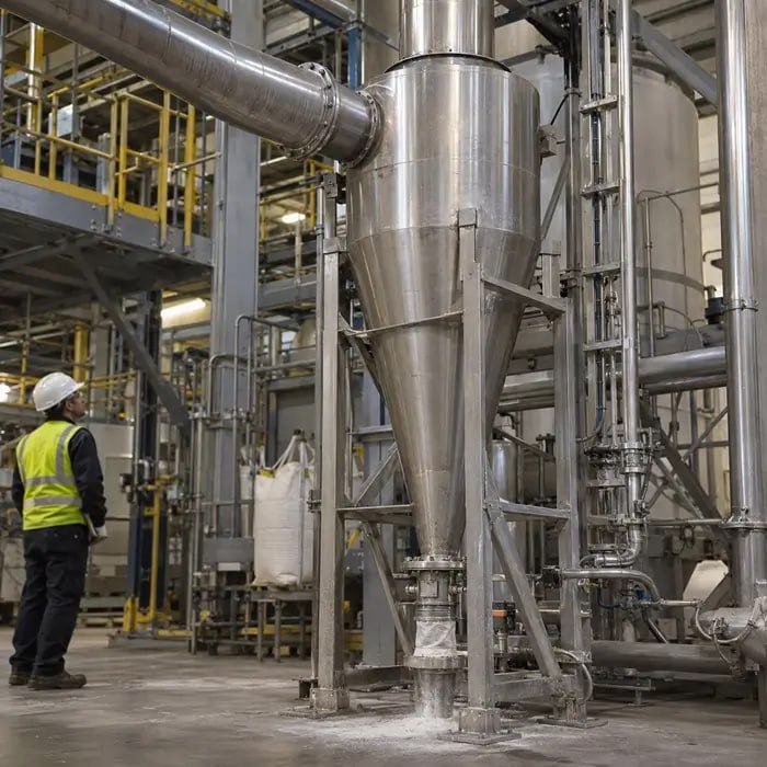
The filter receiver separates the conveyed powder from the gas before the gas reaches the vacuum generator. Filter resistance therefore affects conveying performance, but the way that resistance develops depends strongly on whether the receiver operates cyclically or continuously.
Batch and Continuous Receiver Behavior
Many compact vacuum conveyors, particularly systems used for pharmaceutical and fine-powder transfer, operate as a batch cycle. Powder is conveyed into the receiver, the vacuum is isolated, the collected material is discharged, the filters are cleaned, and the next cycle begins. In these systems, filter cake accumulated during filling can increase resistance and extend conveying time. Still, much of the surface cake should be removed during the cleaning stage before the next cycle.
A progressive loss of performance across multiple cycles therefore points toward incomplete cleaning, depth loading of the filter medium, persistent air leakage, or another change that remains after the normal cleaning sequence. Fine, cohesive, or hygroscopic powders are particularly susceptible to penetration into porous filter media and a gradual increase in base filter resistance. Surface-filtration media, including PTFE-membrane constructions, can reduce depth penetration by keeping more of the collected material on the filter surface where cleaning can remove it.
Continuous vacuum conveying uses a different receiver and discharge arrangement, for example, continuous discharge through a rotary valve or alternating receivers. In that configuration, filter resistance can rise while conveying remains online, directly moving the system operating point and reducing available gas flow. The distinction between cyclic and continuous operation is therefore essential when interpreting increasing filter differential pressure and falling throughput.
For hazardous or low-OEL materials, the primary receiver filter may also be supplemented by a downstream police or high-efficiency filter. This protects the vacuum generator and exhaust side if the main filter is damaged or develops a leak.
Pulse-Cleaning Sequence and Can-Velocity
Pulse cleaning uses a short reverse-flow event to detach accumulated cake from the filter surface. Cleaning effectiveness depends on pulse pressure and duration, filter construction, cake properties, and the gas-flow condition during cleaning.
Can-velocity describes the upward gas velocity through the open passage area of a filter housing. If that upward flow is too high while the filters are being cleaned, detached cake fragments can remain suspended or become re-entrained instead of dropping into the collection zone.
The relevant settling behavior is therefore that of the detached cake or agglomerated fragments, not the terminal settling velocity of the individual primary particles. Applying the settling velocity of a sub-10 micron primary particle as the can-velocity criterion would give an unrealistic design condition for most fine-powder receivers.
Receiver operation also matters. In many cyclic vacuum conveyors, the conveying vacuum is isolated or switched off before filter cleaning and discharge. Under those conditions, there may be little sustained upward conveying flow during the cleaning stage, so can-velocity is less dominant than in a continuously operating receiver or baghouse.
Pulse-cleaning performance should therefore be evaluated for the actual receiver configuration rather than transferred directly from conventional continuous baghouse design. Published work on pulse-jet filtration also shows that nozzle geometry, venturi design, pressure distribution, and filtration conditions affect cleaning performance.
What to Measure When Vacuum Conveying Becomes Unstable
Troubleshooting should first distinguish loss of gas-side performance from a change in powder behavior. Useful operating signals include vacuum-generator inlet pressure, receiver-filter differential pressure, conveying time, transferred mass per cycle or unit time, and gas flow or equivalent free-air delivery where this is measured.
The relationship between these signals is more useful than any single number. Rising filter differential pressure together with deeper pump vacuum and falling transfer rate points toward increasing system resistance. Falling throughput without a corresponding increase in filter resistance can instead indicate air leakage, pickup restriction, changing feed behavior, or a change in the powder itself.
When the Powder May Be Driving the Change
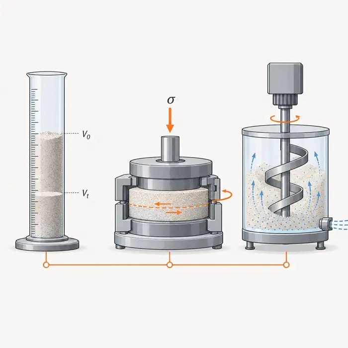
If pickup becomes unstable, powder permeability and deaeration behavior can help determine whether retained air and gas transmission through the powder bed are contributing to surging, flooding, or inconsistent solids admission. If product damage is suspected, particle-size distribution and, where relevant, particle morphology or coating integrity should be compared before and after conveying.
Minimum stable conveying conditions are best established through controlled trials with the actual material. For dilute-phase systems, the test should identify the onset of unstable transport or deposition and establish an operating margin above that condition. For materials capable of dense-phase conveying, trials can determine whether a lower-velocity, higher-solids-loading regime provides a better operating window.
Powder Property and Process Criteria for Vacuum Conveying Selection
The technical case for vacuum conveying rests on material hazard, powder behavior, conveying regime, process configuration, required throughput, and conveying distance. Vacuum is not synonymous with dilute phase: suitable powders can be conveyed under vacuum in dilute, semi-dense, or dense-phase regimes. The selection should therefore begin with the material and process requirement rather than with a universal preference for one pressure mode.
Materials with low occupational exposure limits provide a strong reason to consider vacuum conveying because loss of integrity along the suction line tends to produce inward leakage rather than outward powder release. Pharmaceutical active ingredients, toxic intermediates, and other potent fine materials may therefore benefit substantially from vacuum transfer. The required containment performance still determines the design of pickup, receiver, discharge, isolation, filtration, cleaning, and maintenance interfaces; vacuum operation alone does not establish containment performance.
Combustible Dust, Inerting, and ATEX
Combustible dusts require careful analysis regardless of pressure mode. A vacuum conveying system handling a combustible powder can still contain an explosible dust-air atmosphere inside the pipeline or receiver. HSE guidance on safe handling of combustible dusts (HSG103) addresses the need to prevent and mitigate dust explosions in powder-handling systems. Negative pressure can reduce outward dust release at a breach, but inward leakage becomes a different concern when the system is intentionally inerted because incoming air introduces oxygen and can compromise the inert atmosphere. Explosion protection, isolation, inerting strategy, oxygen monitoring where required, and leak control must therefore be based on the actual dust hazard analysis. Equipment and protective systems placed on the EU market for use in potentially explosive atmospheres must meet the applicable requirements of ATEX Directive 2014/34/EU.
Powder Behavior and Process Configuration
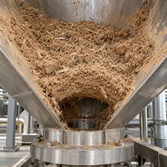
Fine, aerated, or cohesive powders that surge, flood, or feed inconsistently can provide another reason to consider vacuum conveying. Powders with high air retention and low permeability can respond strongly to changes in aeration state and feed conditions, making controlled introduction into the conveying line important. Powder deaeration behavior and fine powder fluidization characteristics both contribute to this instability. A vacuum system with a properly designed pickup and controlled solids admission can offer stable transfer for these materials, but the result depends on feeder design, pickup geometry, air ingress, permeability, and the available conveying conditions rather than on pressure mode alone.
Multi-point pickup is another configuration where vacuum conveying can simplify system design. A common suction line can collect material sequentially from several pickup locations, with individual branches isolated when not in use. Because the pressure gradient draws gas and solids toward the receiver, the arrangement can avoid the need to distribute pressurized conveying gas to every pickup point. Valve design, leakage, branch balancing, and sequencing still determine whether each pickup receives the required airflow.
Hygroscopic or moisture-sensitive fine powders can also be handled in vacuum systems using conditioned or closed-loop conveying gas. Recirculating dry gas can reduce humidity exposure compared with an open-loop system, provided air ingress at the pickup, seals, discharge transitions, and other interfaces is controlled. Moisture control and caking window management therefore becomes part of the conveying-system design when the material is sufficiently sensitive to justify the additional complexity.
When Positive Pressure Remains the Appropriate Choice
Vacuum conveying is constrained by the pressure ratio, flow capacity, and operating range of the selected vacuum generator. Conventional lean-phase vacuum systems generally operate at moderate vacuum levels, while higher-vacuum equipment can support denser, lower-velocity conveying regimes. Dense-phase vacuum conveying is therefore technically established and can be used for suitable materials where low conveying velocity or reduced product degradation is important.
The practical limitation is more often the combination of conveying distance, required capacity, pressure drop, and equipment size. Positive-pressure systems can provide substantially larger pressure differentials and are therefore well suited to long conveying distances and high-throughput transfer. As one equipment example, GEA specifies dense-phase vacuum conveying for distances up to approximately 100 m and dense-phase positive-pressure conveying for distances exceeding 300 m, although actual limits depend on the material and system design.
The containment disadvantage of positive pressure can be acceptable for materials that do not require the inward-leakage behavior provided by vacuum. Appropriate seals, isolation, leak detection, and local engineering controls can provide effective containment for many bulk materials.
For fragile materials, conveying regime is particularly important. Dense-phase positive-pressure conveying can provide low gas velocities and high solids loading over substantial distances, while dense-phase vacuum conveying can provide the same fundamental low-velocity advantage for suitable applications over shorter or moderate distances. The selection between vacuum and positive pressure should therefore account for hazard classification, required containment performance, conveying distance, throughput, powder behavior, available pressure differential, attrition tolerance, filtration requirements, and the engineering controls required at both ends of the system.
References
- Mills, D. Pneumatic Conveying Design Guide. 3rd ed. Butterworth-Heinemann, 2016. DOI: 10.1016/C2014-0-02678-0. View on ScienceDirect.
- Kalman, H. “Attrition of powders and granules at various bends during pneumatic conveying.” Powder Technology, Vol. 112, No. 3, 2000, pp. 244–250. DOI: 10.1016/S0032-5910(00)00298-9. View on ScienceDirect.
- Taylor, T. “Specific energy consumption and particle attrition in pneumatic conveying.” Powder Technology, Vol. 95, No. 1, 1998, pp. 1–6. DOI: 10.1016/S0032-5910(97)03309-3. View on ScienceDirect.
- Andersen, B. O., Nielsen, N. F., and Walther, J. H. “Numerical and experimental study of pulse-jet cleaning in fabric filters.” Powder Technology, Vol. 291, 2016, pp. 284–298. DOI: 10.1016/j.powtec.2015.12.028. View on ScienceDirect.
- Joe, Y.-H., Shim, J., and Park, H.-S. “Evaluation of the can velocity effect on a bag filter.” Powder Technology, Vol. 321, 2017, pp. 454–457. DOI: 10.1016/j.powtec.2017.08.030. View on ScienceDirect.
- Health and Safety Executive. HSG103: Safe Handling of Combustible Dusts: Precautions Against Explosions. 2nd ed., 2003. View HSE guidance.
- European Parliament and Council. Directive 2014/34/EU on the Harmonisation of the Laws of the Member States Relating to Equipment and Protective Systems Intended for Use in Potentially Explosive Atmospheres. Applicable from 20 April 2016. View European Commission ATEX guidance.
- GEA. Vacuum Conveying – Lean Phase. Technical information on dilute-phase vacuum conveying, positive-displacement exhausters, operating vacuum, conveying capacity, and distance. View GEA technical information.
- GEA. Vacuum Conveying – Dense Phase. Technical information on high-vacuum dense-phase conveying, batch receiver operation, low-velocity transfer, capacity, and conveying distance. View GEA technical information.
- GEA. Pressure Conveying – Dense Phase. Technical information on dense-phase positive-pressure conveying, conveying pressure, capacity, and long-distance transfer. View GEA technical information.
- Hosokawa Alpine. Filters for Bulk Materials. Technical information on primary filtration and FPO police filters used to protect downstream equipment, including vacuum generators, following primary-filter failure. View Hosokawa technical information.