
Table of contents

Why creep matters
Powder creep mechanisms are time-dependent and may deform under load. Powders show it in two distinct ways. Loose beds creep through rearrangement and micro-fracture. Sintered parts creep through diffusion and dislocation motion. Aviation performance depends on controlling both behaviors. Designers manage mechanisms and verify behavior with careful tests.
Two regimes in powders
In powders, two regimes dominate. Granular creep occurs in loose assemblies. Diffusion and dislocation creep occur in consolidated parts. Each regime responds to different levers. Each regime also needs specific tests.
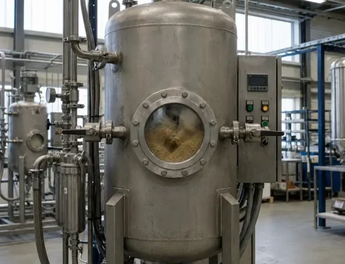
Granular creep in loose powders
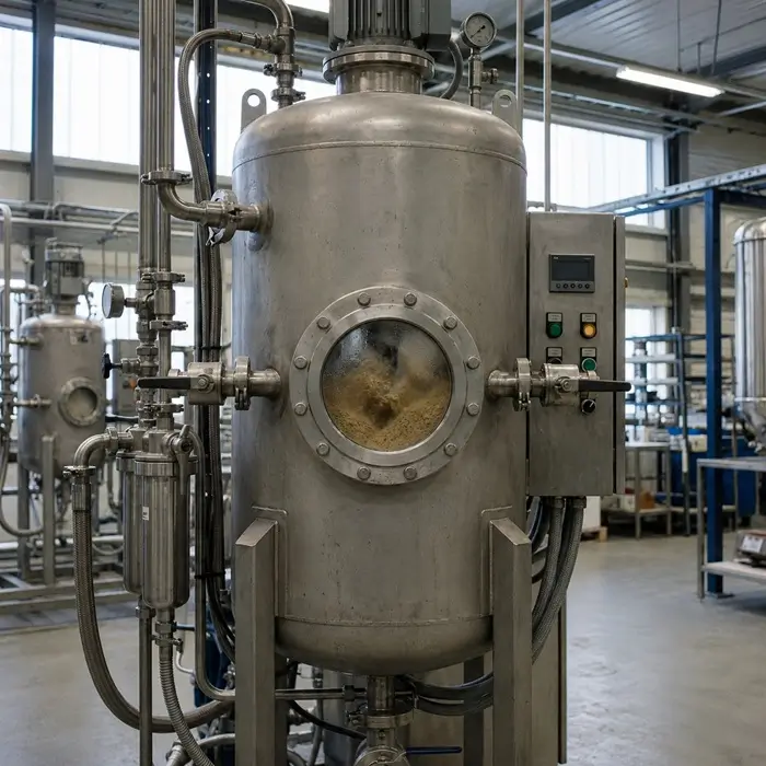
Loose beds creep under constant load in bins and hoppers. Soils on slopes show similar behavior. Particles search for lower energy packings. Contacts age and friction rises. Small fractures create irreversible densification. Strain often follows a logarithmic time trend. Local plastic hot spots drive non-affine motion. Thermal activation is not always necessary. Operations feel the effect in storage and dosing. Flow drifts and bulk density shifts over time.
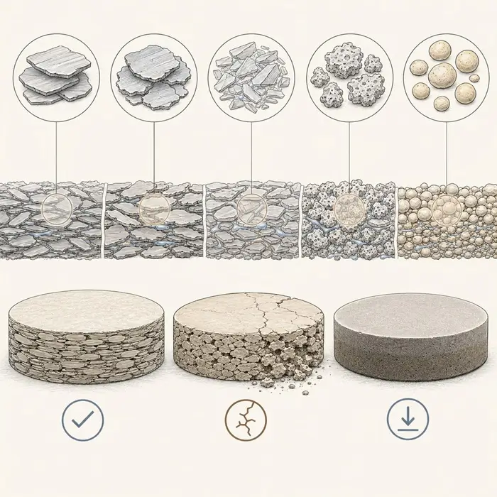
Diffusion and dislocation creep in sintered parts
Consolidated powders bring microstructure into focus. Grain size, porosity, and phases set the rate. Nabarro–Herring uses lattice diffusion of vacancies. The rate scales as one over grain size squared. Fine grains therefore creep faster at high homologous temperature. Coble creep runs along grain boundaries. The rate scales as one over grain size cubed. Ultra-fine grains suffer most at lower temperatures. Dislocation creep rises with higher applied stress. γ′ precipitates slow glide and climb in Ni-base systems. Proper size and volume fraction raise resistance.
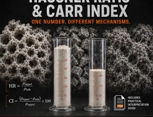
Measurement techniques that reveal mechanisms
Engineers test loose powders in one-dimensional compression. A constant axial load applies stress. LVDTs track displacement over time. Data often show logarithmic-like strain evolution. Temperature control stabilizes the baseline. Consolidated parts need high-temperature creep frames. Tension or compression tests follow standard practice such as ASTM E139—Standard Test Methods for Conducting Creep, Creep-Rupture, and Stress-Rupture Tests of Metallic Materials to report primary, secondary, and tertiary rates. Curves show primary, secondary, and tertiary stages. Reporting separates each stage’s rate. Microstructure explains the curve shapes. SEM and TEM reveal defects and precipitates. X-ray diffraction confirms phase and lattice state. Digital image correlation maps local strain early. Acoustic emission flags damage before visible flow.
For reference data across alloys, use the NIMS Creep Data Sheets to compare curves and rupture lives.
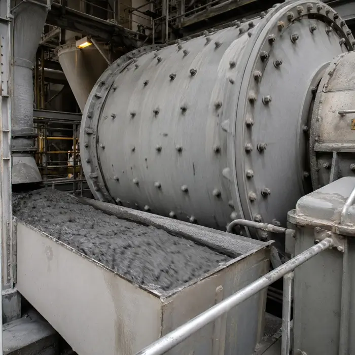
Processing levers that set creep behavior
Start with gas-atomized feedstock for uniform packing. Tight size bands improve green density control. Compaction route matters for pore geometry. Uniaxial pressing, CIP, and HIP give distinct paths. Each route changes pore size and connectivity. Sintering closes porosity and sets grain size. Aging then tunes γ′ in Ni-base systems. Example schedules near 760 °C then 850 °C help. Ni₃(Al,Ti) precipitates form coherent obstacles. They impede dislocation motion and climb. Alloying supports stability against coarsening. Cr, Co, and Re help hold fine dispersions.
Design choices that raise resistance
Balance matrix composition, γ′ fraction, and grain size. Higher γ′ fractions add strong barriers. Orowan looping then needs higher effective stress. Fine grains raise diffusion creep at high T/Tm. Designers sometimes use dual-grain strategies. Less-stressed zones can use finer grains. Highly stressed regions favor coarser grains. Boundary networks resist sliding under shear. Carbides and borides can help. Clean boundaries also reduce damage nucleation.
Recovery, thermal cycling, and re-loading
Creep curves feature three classic stages. Primary shows decreasing rate due to hardening. Secondary holds a near-steady rate. Tertiary accelerates due to damage growth. Unloading recovers elastic strain immediately. Some creep strain may recover by annihilation. Thermal cycles can relieve stored energy. However, cycles can also over-age γ′. Schedules must match alloy state and goals.
Aviation applications and corrections
Aviation uses powder metallurgy routes heavily for disks. Blades are typically single-crystal or directionally solidified castings. That route removes transverse grain boundaries. Creep life improves at blade service temperatures. HIP consolidation improves disk durability. Fatigue and creep both benefit from HIP. Coatings then manage the thermal field. TBC systems use a bond coat first. HVOF or LPPS commonly deposit that bond coat. Ceramic top coats protect the metal further. APS and EB-PVD deliver those top coats. HVOF is not the usual ceramic top-coat route. Additive manufacturing expands the playbook. Laser powder-bed fusion enables local tailoring. Post-processing must optimize γ′ and porosity for creep. Surface finishing also affects damage initiation.
Powder creep mechanisms conclusion
Powder creep mechanisms occur in bins and silos. Sintered parts creep in hot engines. Mechanisms differ across those contexts. Control starts with clean feedstock and packing. Processing then sets pores and grains. Heat treatment builds the right precipitates. Design locks boundary chemistry and network strength. Testing validates every step with data. The result is a predictable life at a certain temperature.
")


