
Table of contents

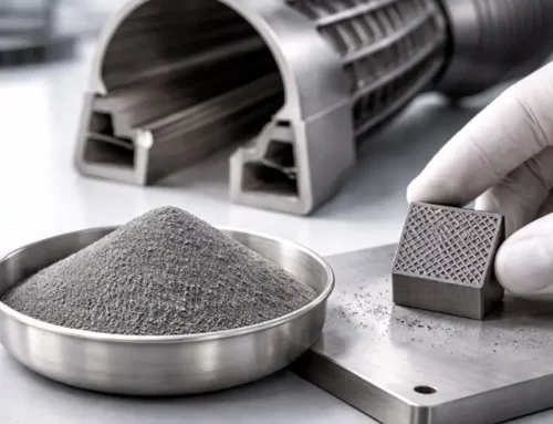
Silicon is back in the anode discussion for one reason. It offers more capacity than graphite. That promise now meets factory reality. Manufacturers are scaling silicon materials, and they are building plants to supply them. This article explains why silicon anode powder is difficult. It also shows what powder specifications matter most. Finally, it maps the manufacturing failure modes that appear first.
Why silicon is different from graphite in the plant
Graphite sets the baseline for modern anode manufacturing. Most plants understand how it flows, disperses, and coats. Process windows, QA checks, and supplier specs reflect that accumulated experience. Silicon forces different rules. During cycling, silicon expands and contracts, and the repeated strain loads binders, conductive networks, and the SEI. Local porosity shifts, so contact pathways change over time. These effects begin at the particle scale, then grow into electrode-level defects.
Three penalties show up early in production. Dispersion errors become visible faster because silicon-rich clusters expand together and crack the coating. Weak binder architecture fails sooner, because adhesion must survive repeated strain. Small shifts in moisture and oxide state also matter more because they can swing rheology and early cycle loss. That history explains the slow adoption curve. Still, scale-up is accelerating because the performance gains justify tighter control.
Silicon anode powder types you will see in real supply chains
Micro silicon vs nano silicon
Nano silicon raises surface area, so it improves kinetics, but it also increases interphase growth and lithium consumption. Consequently, binder fraction and dispersion quality become first-order variables, not formulation details.
Many scaled materials therefore use micro silicon or micro silicon-dominated composites. Lower surface area reduces binder demand and calms slurry yield stress. Moreover, micro silicon usually shows less extreme moisture and oxide sensitivity during storage. Agglomeration also shifts, which can reduce silicon-rich clusters that later crack during formation. Micro silicon still expands, so mechanical fatigue remains unavoidable. Even so, the slower damage progression gives manufacturers a wider coating and calendering window.
Silicon oxide and silicon carbon composites
SiOx and silicon carbon composites aim to buffer expansion. They also reduce direct silicon exposure. That can stabilize the SEI. It can also simplify mixing because the surface chemistry is less extreme. Many scaled materials are silicon-carbon composites. They aim to replace graphite as a drop-in fraction.
What “silicon rich” really means
Marketing language hides practical constraints. Silicon-rich can still mean 5 to 15 percent silicon by mass in the active blend. Above that, yield often drops unless the binder and calendering window are tuned. That tuning is not abstract. It is powder physics plus process stress.
The four powder levers that decide silicon success
Lever 1: Particle size distribution and fines control
Silicon performance depends on PSD shape, not just D50.
Fine tails drive two outcomes.
-
Higher side reaction rates.
-
Higher binder demand per mass.
Coarse tails drive different outcomes.
-
Local current hotspots.
-
Higher crack initiation risk.
A narrow PSD can improve reproducibility. Yet it can also reduce packing flexibility. A broader PSD can pack better, but it complicates dispersion.
Actionable takeaway: treat PSD as a design variable, not a certificate value.
Lever 2: Surface chemistry and oxide growth
Silicon forms an oxide layer under normal handling. That layer can partially passivate the surface, but it also alters surface energy and binder anchoring. In parallel, it can contribute to higher first-cycle loss through increased interphase demand.
In production, oxide matters because it is not constant. It evolves with storage time and exposure, both between lots and within a lot. As oxide state changes, wetting and dispersion shift, which can unexpectedly change slurry viscosity. If viscosity spikes appear without a process change, check oxide history and moisture control before blaming equipment.
Lever 3: Agglomeration and dispersion quality
High surface area silicon often arrives with an agglomerate population. If dispersion does not fully break that population, the electrode contains silicon-rich clusters. Clusters expand together, concentrate stress, and initiate cracking, which then disrupts electronic pathways. That mechanism produces the familiar pattern of swelling scatter and capacity scatter across rolls and lots.
Therefore, dispersion is not only a mixing task. It is a powder QA task, because agglomerate tendency and break-up behavior must be monitored and controlled.
Lever 4: Binder architecture and mechanical integrity
Silicon turns the binder from a glue into a load-bearing network. The polymer must accommodate strain, maintain adhesion, and keep carbon pathways intact as silicon swells and relaxes. In other words, binder choice becomes a mechanical design decision, not only a formulation choice.
That is why binder literature feels heavy. Silicon exposes weak polymer architecture early, especially at practical loadings. A binder can look fine in small-scale screening, yet fail on the line when rheology drifts, coating defects appear, or drying drives binder migration.
Plants feel binder limits across the full operating window. Slurry stability sets mixing and coating consistency. Drying behavior sets the crack risk and distribution uniformity. Calendering sets the mechanical damage and contact quality. Formation then reveals whether the network survives swelling without losing conductivity.
Treat binder selection as part of powder control. Evaluate it against strain tolerance, adhesion stability, and dispersion robustness, not only initial capacity.
Where silicon anode powder breaks in manufacturing
Failure mode 1: Slurry rheology drift that no one can explain
When slurry rheology drifts, troubleshooting often starts with mixing energy, solvent ratio, or operator technique. Silicon introduces additional sensitivity, because surface chemistry and fine-tail variability can change how the solids network forms.
If viscosity correlates with ambient conditions, start with moisture control and powder conditioning. If viscosity shifts with storage duration, review oxide state, exposure history, and lot age as primary variables.
Check out our article: Hard Carbon in Sodium-Ion Batteries: Moisture Control, Powder QA, and Line Readiness
Failure mode 2: Carbon contact collapse
Silicon needs stable electron pathways. Expansion breaks contact points. Carbon networks must be resilient, well-dispersed, and mechanically supported. A silicon electrode can have enough carbon by mass, yet still fail. It fails because the carbon is not where it should be. That is a dispersion and distribution problem.
Practical symptom: impedance scatter rises across coated rolls, while standard visual QC stays quiet. Formation data shows a wider DCIR distribution, and EIS signatures vary more between lanes and along the web. The pattern often correlates with solids distribution, not equipment drift. Silicon-rich agglomerates can create localised expansion and micro-cracking, while carbon-poor regions reduce percolation and increase contact resistance. In practice, the roll looks acceptable until formation exposes the electrical inconsistency.
Failure mode 3: Drying defects that become cycling defects
Many defects begin during drying. Silicon-rich regions shrink unevenly. Binder migrates. Microcracks form. Those cracks turn into fast degradation later.
The fix is rarely “dry slower.” The fix is controlling solids distribution and binder mobility.
Failure mode 4: Calendering that looks fine, then kills the electrode
Calendering increases electrode density and improves initial contact, but it also reduces pore volume. Silicon then has less free volume available during expansion, so local stress rises, and microcracking becomes more likely.
Aggressive calendering can therefore create damage that stays invisible in visual QC. The signal often appears only after formation, when impedance scatter increases and capacity retention diverges.
A useful mental model helps. Calendering optimizes initial contact. Cycling tests whether that contact survives repeated expansion. Those targets are related, but they are not the same.
Failure mode 5: First cycle loss and lithium inventory shock
Silicon drives higher first-cycle loss because interphase formation consumes lithium. That demand rises with surface area and with the fine tail of the PSD. Oxide state and surface functional groups also shift how quickly the interphase grows.
Electrolyte additives can mitigate the effect, but they rarely solve it alone. Control usually starts upstream, by managing the powder properties that set surface exposure and reactivity in the first place.
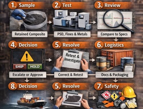
What to test for silicon anode powder, beyond a supplier COA
A COA often lists particle size and purity. That is not enough.
Minimum test set for incoming lots
-
PSD with full curve reporting, not only D10 and D50
-
Surface area, because it predicts binder demand
-
Moisture, plus a defined sampling method
-
Tap density and compressibility trend
-
Microscopy check for agglomerates and hard contaminants
Check out our article on Representative powder sampling.
Nice to have tests that pay off fast
-
Surface chemistry checks for oxide and coatings
-
Rheology screening on a standard slurry recipe
-
Simple adhesion screening after drying
-
Electrical resistivity trend after calendering
The goal is not academic completeness. The goal is early warning.
Handling and EHS realities you should not ignore
Silicon powders can be dusty. Fine silicon can also be reactive. The bigger risk is often not silicon alone. It is silicon plus carbon plus a dry environment.
If you already run dry rooms, you know the pattern. Low humidity increases electrostatic charging risk. Charging increases adhesion and segregation. It also increases nuisance dusting.
Check out our article: Triboelectric Charging in Powders: The science, failure modes, and industrial controls
Check out our article: placeholder: Powder Hazards: Safe Powder Storage and Handling Practices
Related powder control themes in battery manufacturing
Several failure modes described above are not unique to silicon. They are recurring powder control themes in battery manufacturing. Use the links below when you need deeper mechanisms, measurement choices, or control strategies.
-
Dry electrode lines still face binder and dispersion issues, even without solvent.
-
PFAS pressure matters if fluoropolymers appear in the process stack.
-
Sodium ion hard carbon shares the same moisture discipline mindset, even with different chemistry.
-
Sampling discipline decides whether your lab data is real.
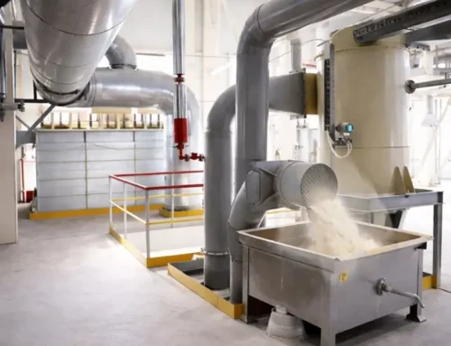
What is actually happening in the market
Industrial capacity for silicon anode materials is now coming online, and the announcements are concrete. Sila began operations at its Moses Lake facility, positioned as an automotive-scale silicon anode plant supplying EV demand. Group14 raised major funding and took full ownership of its South Korea BAM factory, producing SCC55, a silicon carbon composite positioned as a graphite replacement path. BASF and Group14 also announced a joint anode solution built around Group14’s silicon material and BASF’s binder platform, which signals supplier focus on factory integration, not only performance demos. In parallel, LeydenJar launched its pure silicon anode product line for thin form factor devices and continues to expand its commercial footprint.
These milestones matter for powder engineers for one reason. Scale shifts the bottleneck from peak performance to repeatability. Once supply contracts and volume lines enter the picture, silicon succeeds or fails on lot-to-lot stability in PSD tails, surface state, agglomeration behaviour, and binder compatibility.
Closing perspective
Silicon anode powder does not fail because silicon is inherently unstable. It fails when factories apply graphite assumptions to a material that behaves differently under strain.
Graphite tolerates a wider range of sampling quality and dispersion consistency. Silicon does not. It amplifies small weaknesses in powder control, biased samples hide the tails that matter, agglomerates become local stress concentrations, and binder choices collapse when the network undergoes repeated expansion.
Scaling silicon, therefore, starts with powder discipline. Define a specification that reflects the relevant physics, PSD tails, surface area, oxide state, and agglomeration tendency. Then support it with incoming tests and trend controls that detect drift before formation data exposes it.


