Substantially revised and updated October 15, 2026.

A fine powder can block a hopper after settling, then discharge almost like a liquid immediately after filling. The difference is often the gas trapped between its particles.
This uncontrolled discharge, called flooding or flushing, can overwhelm feeders, cause inconsistent package weights, and release dust. The particle bed carries load through contacts when consolidated; elevated interstitial gas pressure reduces those contact stresses, and a once-resistant powder can move suddenly.
Rathbone, Nedderman, and Davidson showed experimentally that powder discharge rates increased with aeration, approaching inviscid-fluid behavior under their fully aerated test conditions [1]. The key engineering question is how the powder retains gas, how long it takes to release it, and what the equipment does during that interval.
Where Does the Entrained Air Come From?
Air enters or redistributes within a powder bed during normal handling. Problems develop when gas cannot escape quickly enough before discharge. Rapid filling and free fall. A long drop can entrain air and leave the bed relatively loose. At high filling rates, the powder may reach the outlet before excess gas pressure has dissipated. Rathole collapse. In funnel flow, material moves through a central channel while powder remains stationary beside it. Collapse of that stagnant region disturbs the bed and can produce sudden discharge.
Pneumatic conveying. Receiving bins may contain aerated powder and excess conveying gas. See PTI’s article on fine-powder fluidization in pneumatic conveying for related behavior. Restricted venting or gas leaking back through discharge equipment can raise pressure at the outlet.
Gas injection and mechanical disturbance. Aeration can reduce resistance to motion, but excessive injection can cause uncontrolled discharge. The timing of the problem often identifies the source [11].
Recognizing Flooding in the Plant
Flooding often appears as a sudden change in discharge rate. A feeder may deliver a stable feed for several minutes, then release excess material. The operating conditions immediately before the event help identify the mechanism.
| Plant observation | Mechanism to investigate | First action |
|---|---|---|
| Sudden discharge after filling | Excess aeration retained in the bed | Compare filling rate, drop height, and hold time |
| Uncontrolled discharge after restricted flow | Rathole collapse and sudden powder movement | Inspect flow pattern and stagnant regions |
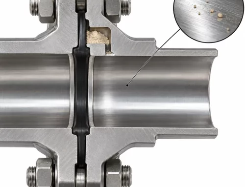
| Flushing near a rotary valve | Returning gas from pressurized rotor pockets or leakage through clearances | Check pressure differences, valve venting, and wear |
| Different behavior between batches | Changes in fines content, packing, or permeability | Compare particle size distributions and permeability |
| Rapid discharge when fresh, restricted flow after settling | Dissipation of aeration and increasing resistance to flow | Compare aerated and consolidated behavior |
Which Powders Are Most Susceptible? The Geldart Classification
The Geldart classification groups powders according to particle size and particle–gas density difference. It describes fluidization behavior, which helps explain why some powders retain aeration while others rapidly settle [2].
| Group | Characteristic behavior | Flooding relevance |
|---|---|---|
| A: Aeratable | Expands readily during aeration and deaerates relatively slowly | Particularly susceptible to retained aeration and uncontrolled discharge |
| B: Sand-like | Begins bubbling near minimum fluidization and loses aeration rapidly when gas flow stops | Retained aeration is generally less important because the bed collapses almost immediately |
| C: Cohesive | Difficult to fluidize uniformly; gas tends to channel through cracks and preferential paths | Strong cohesion encourages arching and ratholing; structural collapse can produce sudden discharge |
| D: Spoutable | Large or dense particles that can form stable spouted beds | Less representative of classic fine-powder flooding |
Group A is the central case for persistent aeration. Group C may also experience localized gas pressure and sudden structural failure, but its behavior is not equivalent to Group A fluidization. Changes in the fines fraction can alter packing, permeability, and cohesion, while segregation can produce local regions with different discharge behavior. Geldart boundaries are not universal flooding limits.
Why the Flow Function Coefficient Is Not a Flooding Index
The flow function coefficient, ffc = σ₁ / σc, is the ratio of major principal consolidation stress to unconfined yield strength. In the classification described by Schulze, ffc below 1 is non-flowing; 1–2 very cohesive; 2–4 cohesive; 4–10 easy-flowing; and above 10 free-flowing [3]. A low ffc indicates greater consolidated strength relative to applied stress, not increased floodability.
Shear testing remains important for arching, ratholing, and hopper design. ASTM D6128-22 describes the Jenike shear test [4]. But ffc does not describe permeability or deaeration and therefore cannot predict how a powder responds to entrained gas.
What About Carr’s Floodability Index?
Carr’s empirical floodability index combines a flowability index, angle of fall, angle of difference, and dispersibility into a screening score [5]. It helps compare grades and flag changes in floodability, but does not incorporate silo depth, fill rate, pressure, feeder geometry, or deaeration time. It cannot establish safe operating conditions for a specific hopper.
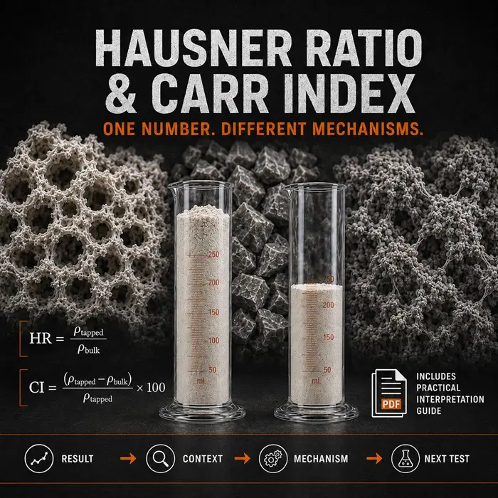
It is distinct from Carr’s compressibility index, which uses bulk and tapped densities and belongs to a separate flowability assessment.
Why Deaeration Time Changes With Silo Depth
A bed can stop settling visibly while excess interstitial gas pressure remains. Powder deaeration matters because Rathbone and Nedderman described rapid bed settlement followed by slower pressure relaxation [6]. In a simplified homogeneous bed with constant permeability and fixed drainage boundaries, pressure relaxation follows diffusion-type behavior: t ∝ L², where L is the effective gas drainage length.
Increasing that length from 0.4 m to 4 m therefore increases the characteristic relaxation time by a factor of 100 under the same assumptions. A laboratory hold time can substantially underestimate the required time in a deep silo. In practice, permeability and porosity change during settlement, and gas escapes through different paths. The relevant length is not necessarily the full silo depth.
To scale up, measure pressure relaxation at representative packing conditions and account for drainage paths, filling rate, and the actual operating cycle. Visible settlement alone does not demonstrate complete deaeration.
Which Measurements Help Assess Flooding Risk?
Permeability relates gas flow to pressure drop through the packed powder. It changes with consolidation and packing, so measurements must represent actual conditions. ASTM D8327-24 describes permeability testing as a function of consolidation using the FT4 [7].
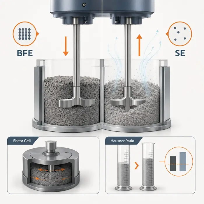
Deaeration testing measures bed settling and the decay of excess gas pressure following aeration. Measuring both distinguishes visible settling from slower pressure relaxation.
Aeration testing determines how the powder’s resistance changes as gas is introduced. A large reduction can reveal sensitivity at gas velocities below full fluidization.
Shear and wall-friction testing establish cohesive strength and hopper-wall interaction needed for reliable mass-flow design.
Particle size analysis reveals fines and segregation. Lloyd and Webb demonstrated that added fines increased the tendency of aerated alumina to develop liquid-like flow at high shear rates; particles of 40 µm and below mattered in their test system, not as a universal threshold [8].
Match the testing program to the symptom. Unstable discharge following filling calls for particular attention to aeration and deaeration; arching after storage calls for consolidated-strength and hopper-flow measurements.
The Opposite Problem: When Fine Powder Discharges Too Slowly
Fine powder can also discharge below the expected rate. In a mass-flow hopper, movement can dilate the bed and require additional gas to enter the expanding voids. This countercurrent gas flow produces a pressure gradient that resists downward powder movement when permeability is low.
Ouwerkerk, Molenaar, and Frank studied this effect in fine fluid catalytic cracking powder. They found that gas drawn into a dilating bed could limit discharge and that introducing controlled gas through a porous hopper section could counteract the adverse gradient [9].
The same low permeability that contributes to retained aeration and flooding can also restrict gravity discharge when the bed needs to dilate.
How to Control Flooding in Practice
The remedy must follow the mechanism: excess gas entering the bed, insufficient time for gas escape, an unstable flow channel, or leakage through the feeder. Five practical levers address these problems.
1. Reduce Air Entrainment During Filling
Use a suitable let-down chute or reduced free-fall distance to limit air entrainment. Check the receiver vent path and its pressure drop: it must accommodate displaced gas as powder accumulates, conveying gas entering the vessel, and any other gas sources.
For a filling rate of 12 metric tons/h and a loose bulk density of 600 kg/m³, incoming powder occupies 12,000 / 600 = 20 m³/h. If the conveying system also delivers 180 actual m³/h at receiver pressure and temperature, the nominal combined gas-handling load is 20 + 180 = 200 actual m³/h.
This assumes the quantities are additive at the same receiver conditions. Final vent design requires peak loading, filter pressure drop, gas retained in powder, additional gas streams, and allowable receiver pressure. The calculation is a gas-volume balance, not a complete vent-sizing method.
2. Establish Hold Time From Deaeration Behavior
Compare discharge immediately after filling with discharge after controlled settling intervals. Establish hold time using representative pressure-relaxation data and the actual gas drainage paths, not simply a laboratory bed-height observation. If the required interval conflicts with production demand, consider a dedicated deaeration stage or changes to the gas escape path.
3. Eliminate Rathole Collapse With Mass Flow
A properly designed mass-flow hopper moves the full contents during discharge and eliminates the stagnant-rathole-collapse mechanism. Determine geometry, outlet size, and feeder withdrawal from measured cohesive strength and wall friction. Steep walls alone do not guarantee mass flow. Mass flow removes one triggering mechanism, but it cannot eliminate flooding from residual aeration or gas leakage.
4. Control Rotary Valve Leakage and Feeder Withdrawal
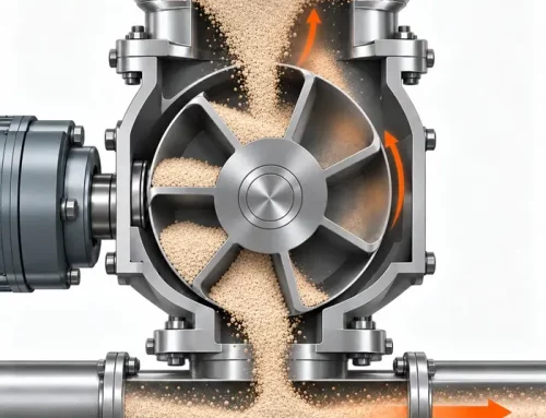
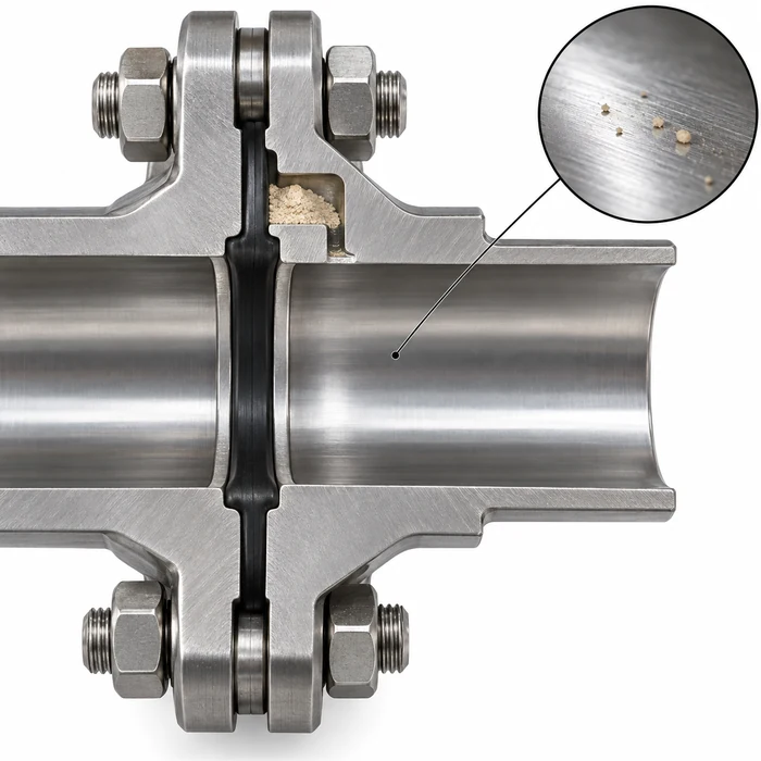
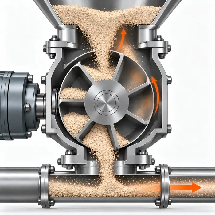
In positive-pressure pneumatic conveying, rotary valve pockets carry pressurized gas from the discharge side back toward the powder inlet. Returning gas and leakage through worn clearances can enter the hopper. PTI also examines these operating problems in rotary airlock clearance, bypass, and attrition. Vent the returning pockets appropriately and inspect valve condition and operating pressure [10].
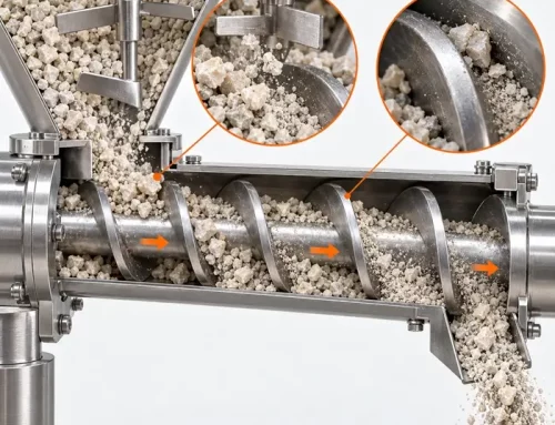
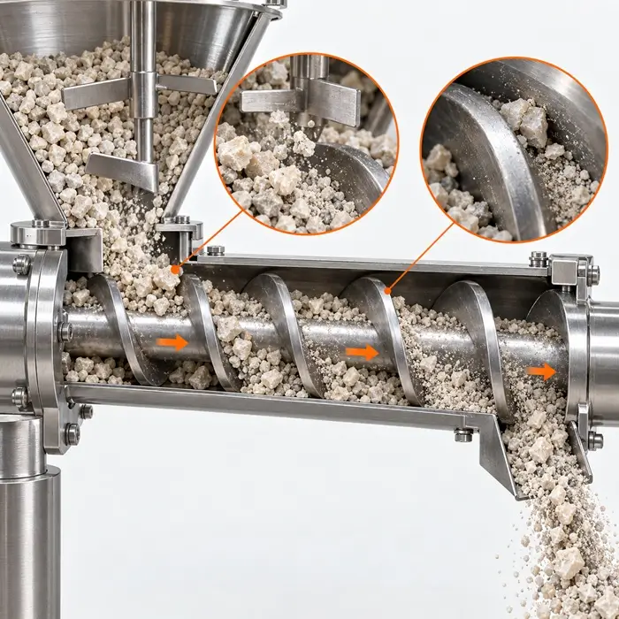
A properly designed screw feeder can provide controlled withdrawal for some aerated fine powders and, where a stable compacted plug is formed, resist gas backflow. Selection depends on throughput, compressibility, and pressure differential rather than feeder type alone.
5. Set a Controlled Aeration State at the Outlet
For powders whose rate is limited by dilation and countercurrent gas flow, controlled gas permeation near the outlet can alter the pressure gradient. Establish the operating point by measuring both discharge rate and stability while adjusting gas pressure and flow. Maximum aeration is not the objective.
A Practical Troubleshooting Sequence
- Record when the problem occurs relative to filling, settling, conveying, and discharge.
- Measure pressure differences; inspect receiver venting, gas injection, and rotary valve leakage.
- Inspect hopper flow patterns for stagnant regions and rathole collapse.
- Compare permeability, deaeration, aeration response, and fines content.
- Use shear and wall-friction measurements before changing geometry or outlet dimensions.
- Test changes individually against discharge stability and required throughput.
Where uncontrolled discharge poses a personnel or process safety risk, secure the equipment before investigating.
Conclusion
Powder flooding is a gas-solid handling problem, not merely very good flowability. Geldart classification and Carr’s index help identify susceptibility, while shear, permeability, aeration, and deaeration measurements reveal different parts of the failure mechanism. Reliable discharge requires controlling powder, gas, hopper, and feeder as one system.
FAQ: Powder Flooding and Flushing
Technical Basis / Sources
- Rathbone T, Nedderman RM, Davidson JF (1987). Aeration, deaeration, and flooding of fine particles. Chemical Engineering Science 42(4):725–736.
- Geldart D (1973). Types of gas fluidization. Powder Technology 7(5):285–292.
- Schulze D (2008). Powders and Bulk Solids: Behavior, Characterization, Storage and Flow. Springer.
- ASTM D6128-22. Standard Test Method for Shear Testing of Bulk Solids Using the Jenike Shear Tester.
- Carr, R. L., Jr. (1965). “Evaluating Flow Properties of Solids.” Chemical Engineering, 72(2), 163–168, January 18. View bibliographic record.
- Rathbone T, Nedderman RM (1987). The deaeration of fine powders. Powder Technology 51(1):115–124.
- ASTM D8327-24. Standard Test Method for Measuring the Permeability of Powders as a Function of Consolidation Using the Freeman Technology FT4 Powder Rheometer.
- Lloyd PJ, Webb PJ (1987). The flooding of a powder: The importance of particle size distribution. Powder Technology 51(1):125–133.
- Ouwerkerk CED, Molenaar HJ, Frank MJW (1992). Aerated bunker discharge of fine dilating powders. Powder Technology 72(3):241–253.
- Wypych PW (2008). Effect of Rotary Valve Leakage on Pneumatic Conveying Performance. Particulate Science and Technology 26(3):257–272.
- Johanson JR (1998). Preventing Powder Flooding and Flushing. Pharmaceutical Online, June 1.