
Table of contents

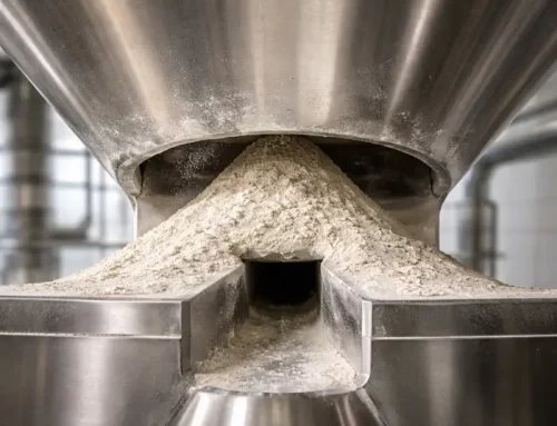
Every solids-handling engineer has seen the problem: a bin has been discharging reliably for months, and then suddenly stops functioning as expected. This unexpected behavior can show up in multiple ways; it flows in fits or empties completely except for a stagnant ring of material clinging to the walls. The cause is often the interaction between wall friction and hopper geometry. For process engineers designing new vessels or troubleshooting existing ones, the question is not whether mass flow is better. It is whether the combination of wall material, hopper slope, outlet size, and powder properties actually delivers mass flow under operating conditions.
The difference between mass flow and funnel flow is not merely an academic distinction. It clearly determines whether the vessel empties, or whether the first powder in is the first powder out, and if segregation damages product uniformity.
What Physically Determines Whether Material Slides or Sticks?
Whether a powder slides or sticks depends on what happens at the wall. As the powder presses against the hopper surface, it creates a normal stress. Gravity then pulls the material downward, while wall friction resists that movement. If the friction is too high, the powder will not slide easily, and stagnant zones can develop.
Wall friction testing measures that resistance directly. The powder is sheared against a sample of the wall material under controlled load, and the force needed to make it move is recorded. Because many powders become more resistant after sitting under load, ASTM D6128 includes both standard wall friction tests and time-based wall friction tests. That matters because a powder that flows during production may behave very differently after a shutdown.
This wall friction angle is important, but only if the angle convention is clear. In the Jenike-based hopper design, wall angle is usually measured from the vertical, not from the horizontal. That means a smaller angle from vertical describes a steeper wall. For example, a wall at 20° from vertical is the same as a wall at 70° from horizontal. Both describe the same slope. Problems start when those two conventions get mixed, because the design can sound steeper or shallower than it really is.
Wall friction angle is also not a fixed material property. It changes with normal stress, wall finish, moisture, and time under load. As Schulze points out, flow properties such as wall friction must be measured over the relevant stress range, not treated as single values. That is why one wall friction result from a clean lab test is often not enough to design or troubleshoot a difficult hopper. A powder may behave very differently once the stress level changes or the material has been sitting in the bin for some time.
How Does Hopper Geometry Convert Wall Friction into Flow Patterns?
The hopper angle that separates mass flow from funnel flow comes from Jenike-based design charts that relate wall friction angle, effective angle of internal friction, and hopper geometry. If the wall friction angle and effective angle of internal friction are known from shear tests, the maximum hopper wall angle against the vertical that still ensures mass flow can be read from those charts. The larger the wall friction angle, the steeper the hopper wall must be to achieve mass flow.
That point matters because wall friction alone does not settle the whole design. Wall friction governs whether the material can slide on the wall. Cohesive strength governs whether the outlet will arch or rathole. Outlet size, therefore, matters alongside wall slope. In practical terms, a reliable mass flow bin needs two things at a minimum: a hopper slope that promotes wall slip and an outlet large enough to prevent cohesive obstructions.
Geometry changes the answer as well. Wedge-shaped hoppers can generally be flatter than conical hoppers for the same material because the stress field is different. Schulze notes that wedge-shaped mass flow hoppers often allow wall angles about 8° to 10° larger against the vertical than conical hoppers with the same material properties. Similarly, flat-walled hoppers with slotted outlets can be 10° to 12° less steep than conical hoppers.
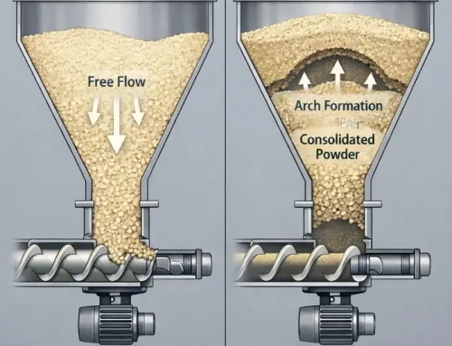
The flow pattern itself develops from the velocity profile. In mass flow, all material moves when any material moves. In funnel flow, only a central channel moves while material outside that channel remains stagnant until later in discharge. Those stagnant zones are what create wide residence time distribution, segregation risk, and ratholing behavior.
Why Does Wall Friction Change with Time and Conditions?
Time is an important variable in many wall friction problems. Powders that sit under load do not always behave the same way they do in an instantaneous test. ASTM D6128 includes wall friction time tests specifically because the shearing force can increase after the sample remains loaded against the wall material for a defined period. In practice, that means a hopper that discharges during the shift can still fail after a weekend shutdown.
Surface condition matters too. Stainless steel starts out smooth, but service changes it; corrosion, wear, product buildup, cleaning history, and wall damage can all alter the effective wall material seen by the powder. If the lab coupon is clean and polished while the plant wall is roughened or coated, the measured value may no longer represent the real hopper. Testing representative surfaces is, therefore, far smarter than trusting catalog descriptions of wall finishes.
Moisture changes everything. Relative humidity, condensation, or temperature cycling can shift adhesion and wall friction enough to move a marginal design across the mass flow boundary. That is one reason the theoretical mass flow line should not be treated as a comfortable target. It is a limit, not a cushion.
What Happens When You Get the Interaction Wrong?
Funnel flow is not just a different flow pattern. It brings specific problems that damage process control. Ratholing is the obvious one. A central channel empties while the surrounding material remains stationary. If the powder has enough cohesive strength, the channel can collapse into a stable obstruction, and flow stops. ASTM D6128 explicitly lists arching and ratholing among the common failures tied to poor solids flow, and Schulze links funnel flow with stagnant regions and the resulting flow problems.
Segregation is more subtle but equally damaging. During filling, particles can separate by size or density. In a funnel flow bin, the moving channel pulls preferentially from one region of the stored material, while other regions remain parked until much later. Schulze notes that this creates different particle size distributions through discharge, whereas mass flow reduces the effect significantly because the segregated material is remixed as it moves downward in the hopper.
Flooding can show up with fine powders. Air retained in stagnant or recently collapsing regions can destabilize discharge and upset feeder control. Residence time also becomes nonuniform. In funnel flow, some material passes through quickly, while material in stagnant zones remains for hours or days. For temperature-sensitive, reactive, or moisture-sensitive products, the residence time spread alone can make the design unacceptable.
How to Measure Wall Friction Correctly?
The Jenike shear tester remains a standard tool because it gives wall friction data with clear physical meaning. In a wall friction test, the sample is sheared over a coupon of the actual wall material under controlled normal load. By plotting shear stress against normal stress, the wall friction relationship can be established over the relevant stress range. The point is not to get one number; the point is to understand how the powder behaves across the loads the hopper actually handles.
Details matter. The wall coupon should match the actual wall material and finish. The tests should cover the stress range expected in service. If the material may sit in the vessel, wall friction time tests should be included. If humidity or temperature varies in production, testing at those conditions is far more valuable than testing only at comfortable lab ambient conditions.
What Design Decisions Follow from the Measurements?
Once the wall friction angle and the effective angle of internal friction are known, the design path becomes clearer. Use the mass flow charts to determine the maximum allowable hopper wall angle against the vertical. Use flow function data to size the outlet against arching or ratholing. Then check whether the feeder withdraws material uniformly across the outlet. A hopper can be steep enough for mass flow and still perform badly if the outlet is too small or the feeder interface is poor.
Avoid designing directly on the theoretical line. Chemical Engineering recommends a safety margin of about 3° for round or square outlets because small changes in powder properties can push a bin from mass flow into funnel flow. That advice is worth taking seriously, especially when raw material variability, humidity swings, or wall wear are likely.
If the required hopper is too steep for the available headroom, engineers still have options. Change the wall surface. Use a liner. Move from a conical hopper to a wedge-shaped geometry. Or accept that funnel flow will remain and design around it with inserts, a live bottom, or a properly engineered feeder arrangement. The key is to make that choice consciously, not accidentally.
What Mistakes Do Engineers Make Most Often?
The first mistake is assuming wall friction is constant. It is not. It changes with stress, time, wall condition, and environment. Measuring one point and designing around it guarantees very little.
The second mistake is ignoring the angle convention. If one engineer speaks in degrees from vertical and another speaks in degrees from horizontal, the same hopper can suddenly sound either steep or shallow. That confusion usually does not stay in the meeting room. It ends up in fabricated steel.
The third mistake is treating the hopper angle as the only variable that matters. As is clear by now, this is not the case. Wall friction determines whether material slides on the wall, the outlet size controls arching risk, and feeder design controls how the outlet is actually withdrawn. Mass flow is a system result, not a single dimension.
The fourth mistake is trusting published values. Literature data can be useful for orientation, but your powder, your wall finish, your humidity, and your operating cycle are what matter. Measure your own material against your own surface.


