Editorial update (October 17, 2026)

An aerospace manufacturer producing Inconel 718 fuel-nozzle components by laser powder bed fusion (LPBF) transfers production to a machine with a larger build plate. After the move, computed tomography (CT) inspections reveal more near-surface lack-of-fusion (LOF) defects. The manufacturer needs to find out what changed. Is the shielding gas still removing spatter effectively across the larger build plate? Has recovered powder become contaminated? Or are the defects caused by changes in powder spreading or melting behavior?
About this worked example: The aerospace producer is hypothetical. Research findings come from published studies, while the operating settings, decision thresholds, and powder-disposition results are illustrative. They are not measurements from an actual production program or generally applicable acceptance criteria.
When Recovered Powder Becomes a Production Problem
Reused powder is an obvious place to investigate, but the number of times it has passed through the machine tells only part of the story. Powder recovered from different locations can have very different exposure histories, even when it comes from the same build. PTI’s guide to virgin and reused powder blend ratios examines why the blend ratio alone cannot describe that history. Gruber and colleagues compared virgin, used, overflow, and spatter powder from an Inconel 718 LPBF process [1]. Used and overflow powder had broadly similar characteristics, but the spatter fraction was substantially more degraded.
| Property | Virgin powder | Spatter powder |
|---|---|---|
| Oxygen content | 250 ppm | 690 ppm |
| Oxygen limit applied in the study | 400 ppm | 400 ppm |
| Laser absorption | Reference condition | Approximately 10 percentage points higher |
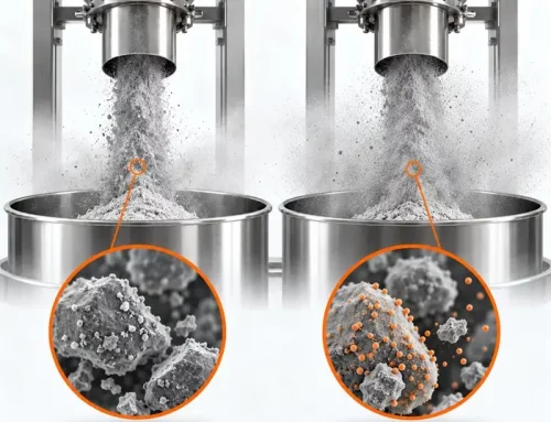
Source: Gruber et al. [1]. The 400 ppm oxygen limit applies to the reported study. It is not a universal acceptance limit for Inconel 718 powder. The spatter powder exceeded that limit by 290 ppm and showed aluminum oxide spots on its particle surfaces. Such changes may affect how consistently the powder melts and spreads during processing. For the manufacturer in this example, the investigation must establish whether similar changes have occurred in its recovered powder and, separately, whether they have anything to do with the increase in defects.
How Spatter Changes Powder Quality
During LPBF, the laser melts selected regions of a powder layer. Metal vapor generated at the interaction zone can entrain surrounding particles, while molten material may also be ejected from the melt pool. A high-speed imaging study identified vapor-driven gas entrainment as an important mechanism behind particle ejection [2].
Recoil pressure and Marangoni-driven flow can also contribute to the ejection of molten material [3]. Some ejected particles leave the build region with the shielding-gas flow. Others return to the powder bed or settle on the part. Hot particles may oxidize during flight or solidification, while resolidified droplets can take on irregular shapes or form agglomerates. Chen and colleagues measured 608 ppm oxygen in Inconel 718 powder collected at the gas outlet, compared with 240 ppm in virgin feedstock [3]. X-ray photoelectron spectroscopy (XPS) also revealed aluminum-rich and chromium-rich oxide signals in the outlet powder.
The same study found that powder collected from geometries with large overhang areas or high surface-to-volume ratios showed greater oxygen uptake. The amount of degradation therefore depended partly on the geometry exposed during the build. A powder batch that has been through five builds is not necessarily in worse condition than one that has been through three. The spatter generated during those builds, and where the recovered powder was collected, also matter.
Establishing the Cause of the Defects
The rise in LOF defects coincided with the move to a larger machine, but that does not prove spatter contamination caused them. Inadequate melting, uneven powder deposition, and differences in chamber gas flow are also plausible explanations. The producer therefore examines the manufacturing process, recovered powder, and finished components rather than treating elevated powder oxygen as a diagnosis on its own.
| Evidence | Alloy in cited research | What it contributes |
|---|---|---|
| Oxygen content and surface oxidation [1,3] | Inconel 718 | Direct evidence of spatter-associated powder degradation |
| Geometry-dependent oxygen uptake [3] | Inconel 718 | Evidence that geometry affects exposure of recovered powder |
| High-speed particle tracking [4] | LPBF demonstration | Measurement of spatter direction, velocity, and trajectories |
| Gas-flow and scan-direction effects [5] | Ti-6Al-4V | Process sensitivities requiring validation for Inconel 718 |
| Coarse spatter particles [6] | Hastelloy X | Evidence that sieving can remove some oversized spatter |
| Spatter overlapping feedstock sizes [7] | Steel powder | Evidence explaining why size separation may be incomplete |
The alloy distinction matters. Results from Ti-6Al-4V, Hastelloy X, and steel help explain spatter mechanisms and measurement approaches, but they do not establish suitable processing conditions for Inconel 718.
Mapping Gas Flow Across the Build Plate
The first check is whether the larger build area contains regions where shielding gas fails to carry spatter away effectively. Where machine access allows, the producer can measure local gas velocities using anemometry or other suitable flow-measurement methods. Computational fluid dynamics (CFD) can help identify recirculation and stagnant zones, although predictions should be checked against measurements. Particle tracking or witness-particle experiments may provide further evidence. The resulting flow map is compared with recorded spatter trajectories and the locations of CT-detected defects. Barrett and colleagues demonstrated a stereovision method capable of estimating three-dimensional spatter trajectories, providing information that cannot be obtained from a single camera view alone [4]. If the producer repeatedly finds spatter accumulation and LOF defects in regions with poor particle removal, it has a reason to investigate gas-flow changes. Controlled builds would still be needed to establish whether improving the flow actually reduces defects.
Separating Contamination From Poor Powder Spreading
Powder chemistry is only part of the investigation. Irregular particles, agglomerates, and changes in the fine-particle fraction can also affect how evenly powder spreads across the build plate. A poorly deposited layer may leave too little material in certain regions, creating another possible route to LOF defects even when powder oxygen content remains acceptable. The distinction between powder condition and recoater behavior is examined further in Powder Spreading in PBF: What Recoater Interaction Reveals.
The producer compares virgin and recovered powder for particle size distribution, morphology, oxygen content, apparent density, and flowability. PTI’s Test Methods hub helps connect these measurements with the engineering question, while the Particle Behavior hub explains their influence on powder performance. ISO/ASTM 52907:2019 provides methods for characterizing metallic additive manufacturing feedstocks, including used powder [8]. ASTM E1019-24 covers applicable inert gas fusion methods for determining oxygen in nickel alloys [9].
Flowability must be interpreted in the context of the test used. A powder that passes a conventional flow-time measurement may still spread poorly under the recoating conditions of a particular machine. The manufacturer therefore needs to examine actual powder-layer quality as well as laboratory measurements.
Why Changing Laser Parameters Is Not a Simple Fix
The producer considers adjusting laser power, scan speed, and hatch spacing in an attempt to reduce spatter. One proposed change lowers power from 300 W to 250 W and increases hatch spacing from 50 µm to 70 µm. These are illustrative settings, not values taken from a qualified Inconel 718 process. The relationship between these variables is commonly expressed through nominal volumetric energy density:
E = P / (v × h × t)
Where P is laser power, v is scan speed, h is hatch spacing, and t is layer thickness. If layer thickness remains constant and the producer wants to maintain the original nominal energy density, the new scan speed must satisfy:
v₂/v₁ = (250/300) × (50/70) ≈ 0.595
The scan speed would have to fall to approximately 59.5% of its original value, a reduction of 40.5%. That keeps the calculated energy density constant. It does not guarantee the same melt-pool dimensions, track overlap, thermal behavior, or spatter generation.
Scan Orientation and Laser Settings Interact
Emminghaus and colleagues investigated this distinction using Ti-6Al-4V. They compared laser-power and scan-speed combinations at a constant nominal energy density of 66.67 J/mm³ [5].
| Laser power | Scan speed | X: Perpendicular to gas flow | Y: Parallel to gas flow |
|---|---|---|---|
| 140 W | 700 mm/s | 379 | 599 |
| 200 W | 1,000 mm/s | 203 | 209 |
| 260 W | 1,300 mm/s | 195 | 43 |
Source: Emminghaus et al. [5], Table 5. The values are detected spatter trajectories from individual Ti-6Al-4V build jobs, not replicated measurements. The camera detected illuminated particles rather than every particle ejected. At 140 W, scanning parallel to the gas flow produced more detected trajectories than perpendicular scanning: 599 against 379. At 260 W, the ranking reversed, with 43 during parallel scanning and 195 during perpendicular scanning.
The counts were nearly identical at 200 W, suggesting an apparent crossover within the tested range. Increasing laser power and scan speed together also reduced detected trajectory counts in both scan orientations, despite the calculated energy density remaining unchanged. The results show that scan orientation and laser parameters interact. Neither can be optimized independently, and equal nominal energy density does not mean equal spatter behavior.
Because these measurements came from individual Ti-6Al-4V builds, they cannot be used to predict the optimum settings for Inconel 718. They do, however, give the hypothetical producer a reason to test its proposed 250 W condition rather than assume it will reduce spatter. Any new settings must be evaluated for melt-pool behavior, powder-layer quality, porosity, component geometry, and the mechanical properties required by the qualified process.
Deciding Which Powder Can Be Reused
The producer now has to decide what happens to the recovered powder. Which material can return to production, which needs further testing, and which should be kept out of the reuse stream? A documented decision framework helps prevent borderline material from being released simply because it passed one measurement. The broader feedstock considerations are covered in Metal Powder Feedstock Quality in Additive Manufacturing. The following example uses hypothetical thresholds.
They are not recommended industry limits. The assumed 400 ppm oxygen acceptance limit is used to make the classification transparent; an actual manufacturer must establish its limits from the applicable feedstock specification, measurement uncertainty, and process-qualification requirements.
Illustrative Powder Disposition Rules
| Condition | Illustrative rule | Decision |
|---|---|---|
| Recovered powder O₂ at or below 300 ppm | Internal screening criterion, subject to the measurement decision rule | Continue full feedstock evaluation |
| Recovered powder O₂ above 300 ppm | Internal caution threshold | Quarantine and investigate |
| Recovered powder O₂ above 400 ppm | Assumed program acceptance limit | Reject from the qualified reuse stream |
| Powder collected at the gas outlet | Classified as spatter-rich | Segregate; do not return to qualified feedstock |
| Overhang area above 25% of projected build area | Illustrative geometry trigger | Increase sampling and review spatter monitoring |
| Unacceptable flowability, apparent density, morphology, or layer quality | Outside qualified process limits | Hold powder or build pending investigation |
| Proposed laser or gas-flow modification | Change to qualified process | Require validation and applicable requalification |
All numerical thresholds are hypothetical and process-specific. In particular, the 25% overhang trigger is not a validated literature limit. Chemical decisions must account for measurement uncertainty and representative sampling. Where more than one rule applies, the most restrictive disposition governs. A powder batch measuring below the 300 ppm screening threshold still needs to meet the remaining feedstock requirements. Similarly, a result above the internal caution threshold does not automatically mean permanent rejection. Quarantine allows the producer to confirm the measurement, investigate the powder’s history, and establish whether any recovery procedure is permitted under its qualified reuse plan.
Worked Disposition Example
Consider four powder streams recovered during the hypothetical investigation.
| Powder stream | Illustrative O₂ result | Disposition |
|---|---|---|
| A: Main recovered-powder stream | 270 ppm | Eligible for further qualification checks |
| B: Powder from a high-overhang build | 340 ppm | Quarantine and investigate |
| C: Outlet-collected spatter-rich powder | 640 ppm | Segregate and exclude from reuse |
| D: Powder recovered after a candidate process change | 295 ppm | Hold for confirmatory testing |
These values are constructed examples, not measurements from a published study or an actual manufacturer. Stream A can proceed to the remaining feedstock checks, including morphology, apparent density, flowability, and suitability for spreading. Stream B exceeds the internal caution threshold and is quarantined, even though its measured oxygen content remains below the assumed 400 ppm acceptance limit. Stream C is excluded both because of its collection source and its elevated oxygen content. Stream D is more difficult. Its measured oxygen content of 295 ppm is close enough to the 300 ppm caution threshold that measurement uncertainty may affect classification. The producer therefore holds the powder for confirmatory testing under its established decision rule. Even if further testing places Stream D clearly below the threshold, the result says nothing about whether the modified manufacturing process is qualified. That requires separate validation against the approved baseline. The uncertainty and any guard band must be established from the actual method, laboratory performance, and sampling procedure. There is no single uncertainty value that can safely be applied to every oxygen measurement.
Testing Whether the Proposed Changes Work
Before changing production, the manufacturer needs evidence that its proposed controls improve the process without introducing other problems. It plans controlled comparisons of the existing configuration against changes to gas-flow distribution, laser parameters, and powder segregation. The changes are investigated separately before combinations are considered. Repeated builds at selected plate locations and representative part geometries help distinguish genuine effects from build-to-build variation. Wherever possible, the producer keeps powder lots, collection procedures, and measurement conditions consistent.
| Measurement | Purpose | Decision supported |
|---|---|---|
| Gas velocity and flow distribution | Identify poor particle removal | Retain or reject gas-flow modification |
| Spatter trajectories and deposition | Compare spatter behavior | Determine whether redeposition has fallen |
| Bulk oxygen and surface chemistry | Assess powder degradation | Quarantine, reject, or continue evaluation |
| Particle size, morphology, apparent density, and flowability | Check feedstock consistency | Determine suitability for reuse |
| Powder-layer quality | Identify spreading problems | Accept or reject proposed handling or process changes |
| CT defect distribution | Assess part integrity | Compare against qualified baseline |
| Mechanical testing where required | Confirm component performance | Support qualification decisions |
Fewer detected spatter trajectories would be encouraging, but not conclusive. The changed settings might still produce inadequate melting or poor mechanical properties. Likewise, lower recovered-powder oxygen would not prove that the LOF problem had been solved. A process change is accepted only when the required powder and component properties have been demonstrated under the applicable qualification procedure.
What the Producer Decides
Based on its illustrative investigation and disposition rules, the manufacturer establishes five controls.
First, powder collected at the gas outlet is kept out of the qualified reuse stream.
Second, recovered powder above the internal oxygen caution threshold is quarantined. Borderline results require confirmatory testing, and powder cannot be released unless its chemistry, particle characteristics, apparent density, flowability, and spreading behavior meet the applicable requirements.
Third, builds exceeding the provisional geometry trigger receive additional sampling and spatter monitoring. The producer will review that trigger when sufficient process data become available.
Fourth, proposed changes to gas-flow hardware or laser parameters remain outside routine production until controlled trials demonstrate acceptable results against the qualified baseline.
Fifth, powder chemistry and spatter-monitoring data are assessed alongside layer quality and CT defect locations. This reduces the risk of blaming spatter contamination for defects that may instead arise from poor spreading or changes in melting behavior.
These are decisions the hypothetical producer can make on the basis of the proposed control framework. They are not evidence that the manufacturer has already reduced scrap, improved powder quality, or qualified a new process.
Powder Reuse and Aerospace Qualification
For aerospace components, passing an internal powder test is not enough. Reused feedstock must comply with the applicable material requirements, and any process changes must remain within the relevant qualification and change-control arrangements. ASTM F3055-14a(2021) specifies requirements for additively manufactured nickel alloy UNS N07718 components produced by powder bed fusion [10].
SAE AMS7003A, revised August 2022, establishes process controls for repeatable production by laser powder bed fusion [11]. ASTM F3592-23 addresses metal powder bed fusion feedstock reuse and sampling strategies [12]. SAE AMS7031, issued March 2022, covers batch processing of used metal powder for reuse in non-closed-loop additive manufacturing machines, including aerospace applications [13]. In the United States, FAA Advisory Circular AC 33.15-3, issued June 23, 2023, describes an acceptable, but not mandatory, means of showing compliance for powder bed fusion aircraft engine parts [14]. It addresses powder traceability, reuse limits, and evidence that components remain acceptable at the defined reuse limits.
EASA Certification Memorandum CM-S-008 Issue 04, issued September 3, 2025, provides European guidance on additive manufacturing certification [15]. UK applicants should confirm the applicable expectations with the Civil Aviation Authority. The producer therefore cannot implement its proposed changes simply because laboratory measurements look promising. Modifications to gas-flow hardware, laser settings, scan strategies, or powder-handling procedures must be evaluated against the qualified manufacturing process and applicable approval requirements.
Conclusion
The increase in near-surface defects after moving to a larger LPBF build plate gave the hypothetical producer several possible causes to investigate. Spatter contamination was one of them, but the available evidence did not establish it as the root cause.
The producer’s next steps are nevertheless clear. Keep spatter-rich powder out of the reuse stream, hold questionable batches for further testing, and investigate whether gas flow, scanning conditions, or powder spreading are contributing to the defects. Any changes to the process must then be tested against the qualified baseline. The difficult part is not deciding which measurements to make. It is establishing what those measurements mean for the powder that can be reused and the parts that can be accepted.
Frequently Asked Questions
Technical Basis / Sources
[1] Gruber K, Smolina I, Kasprowicz M, Kurzynowski T. Evaluation of Inconel 718 Metallic Powder to Optimize the Reuse of Powder and to Improve the Performance and Sustainability of the Laser Powder Bed Fusion (LPBF) Process. Materials. 2021;14(6):1538. Source
[2] Ly S, Rubenchik AM, Khairallah SA, Guss G, Matthews MJ. Metal vapor micro-jet controls material redistribution in laser powder bed fusion additive manufacturing. Scientific Reports. 2017;7:4085. Source
[3] Chen Z, Raza A, Hryha E. Influence of part geometry on spatter formation in laser powder bed fusion of Inconel 718 alloy revealed by optical tomography. Journal of Manufacturing Processes. 2022;81:680–695. Source
[4] Barrett C, Carradero C, Harris E, McKnight J, Walker J, MacDonald E, Conner B. Low Cost, High Speed Stereovision for Spatter Tracking in Laser Powder Bed Fusion. Proceedings of the 29th Annual International Solid Freeform Fabrication Symposium. 2018. Source
[5] Emminghaus N, Klügel T, Hermsdorf J, Kaierle S. Stereo-based image processing for spatter detection in PBF-LB/M of Ti-6Al-4V. RTe Journal. 2024. Source
[6] Raza A, Schwerz C, Pauzon C, Nyborg L, Hryha E. Effect of layer thickness on spatters oxidation of Hastelloy X alloy during powder bed fusion-laser beam processing. Powder Technology. 2023;422:118461. Source
[7] Gadde D, Elwany A, Du Y. Deep Learning to Analyze Spatter and Melt Pool Behavior During Additive Manufacturing. Metals. 2025;15(8):840. Source
[8] ISO/ASTM 52907:2019. Additive manufacturing — Feedstock materials — Methods to characterize metal powders. Source
[9] ASTM E1019-24. Standard Test Methods for Determination of Carbon, Sulfur, Nitrogen, and Oxygen in Steel, Iron, Nickel, and Cobalt Alloys by Combustion and Inert Gas Fusion Techniques. Source
[10] ASTM F3055-14a(2021). Standard Specification for Additive Manufacturing Nickel Alloy (UNS N07718) with Powder Bed Fusion. Source
[11] SAE International. AMS7003A. Laser Powder Bed Fusion Process. Revised August 5, 2022. Source
[12] ASTM F3592-23. Standard Guide for Additive Manufacturing of Metals – Powder Bed Fusion – Guidelines for Feedstock Re-use and Sampling Strategies. Source
[13] SAE International. AMS7031. Batch Processing Requirements for the Reuse of Used Powder in Additive Manufacturing of Aerospace Parts. Issued March 29, 2022. Source
[14] Federal Aviation Administration. AC 33.15-3. Powder Bed Fusion Additive Manufacturing Process for Aircraft Engine Parts. June 23, 2023. Source
[15] European Union Aviation Safety Agency. Certification Memorandum CM-S-008 Issue 04. Additive Manufacturing. September 3, 2025. Source