
Table of contents

A silicon-carbon battery is a lithium-ion battery that uses a silicon-based material composited with carbon as the negative electrode. This design leverages silicon’s exceptionally high theoretical capacity, roughly 3,579 mAh g⁻¹ for the fully lithiated Li15Si4 reference phase, versus graphite’s 372 mAh g⁻¹. The goal is higher energy density and faster charging. In practice, the path from lab promise to mainstream phones is blocked by material-level degradation that becomes acute in compact, safety-critical devices. For phone design, process, and quality engineers, silicon-carbon evaluation is a trade between performance gains and reliability risk.
Why silicon volume expansion is the primary failure mechanism
The dominant failure mechanism is silicon’s extreme swelling during lithiation. Silicon can expand by more than 300% as it alloys with lithium to form LixSi phases, while graphite expands only around 10%. That repeated volume change loads the anode mechanically, stresses the conductive network, and pushes against the cell stack.
In practice, the stress fractures the silicon particles and breaks the electrical contacts. It also repeatedly fractures the passivating SEI layer. Each fracture exposes fresh silicon to electrolyte, which consumes lithium and solvent to rebuild SEI. Capacity drops irreversibly, internal resistance rises, and heat generation increases. Over time, the cell can swell, which is a direct safety and packaging risk in slim phones.
For manufacturing engineers, expansion is not only a material property. It becomes a production problem. It increases delamination risk at the current collector, raises and varies stack pressure, and increases the chance of casing distortion if the mechanical design cannot absorb repeated strain. Severity scales strongly with silicon particle size, silicon fraction, and depth of lithiation per cycle.
The SEI adds another layer of complexity. It is rarely a single uniform film. It often forms a mosaic or bilayer structure with organic and inorganic components. That structure must remain ionically conductive while also surviving large strains, and it often fails to meet that requirement in high-silicon-content systems.
How to measure and quantify silicon carbon battery issues
Engineers need to characterize both intrinsic material behavior and full cell performance.
Structural and imaging diagnostics
-
In situ or operando SEM can reveal particle cracking and loss of contact during cycling.
-
In situ or operando XRD helps track phase evolution, including shifts between amorphous LixSi states during repeated lithiation and delithiation.
Electrochemical diagnostics
-
Cycling tests quantify fade rate and capacity retention under defined windows.
-
Electrochemical impedance spectroscopy tracks SEI-related resistance growth and interfacial changes.
-
Dilatometry measures electrode or cell thickness change directly, which connects swelling to phone packaging constraints.
-
Coulombic efficiency is a critical screen. A low first-cycle CE and unstable subsequent CE usually indicate excessive SEI formation. For long-life consumer targets, teams often aim for sustained CE near 99.9% once the system stabilizes, but the acceptable value depends on duty cycle and OEM warranty targets.
Post mortem verification
Post-mortem teardown of cycled cells can reveal delamination, particle isolation, and electrolyte decomposition patterns. Together, these results form a degradation profile that you can tie to process conditions, silicon fraction, and the composite architecture.
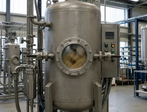
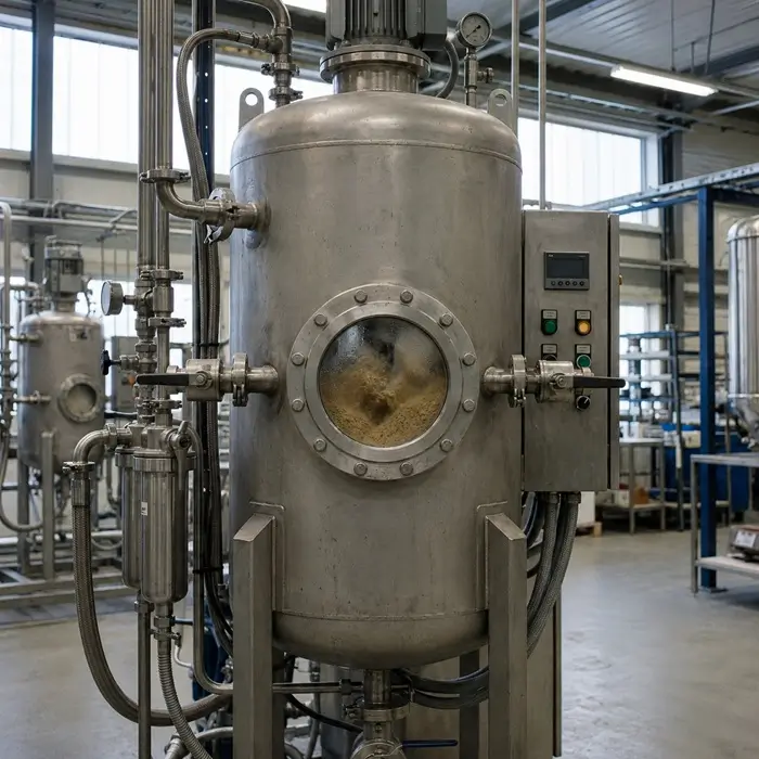
In production R&D, engineers often add screening tools for faster iteration. For example, electrode swelling test systems can quantify expansion in real time under controlled pressure. Slurry gas monitoring can detect micro-liter level gas evolution during mixing, which is a common failure mode with reactive nano silicon and can lead to coating defects. Powder resistivity and compaction density testing can help predict how a silicon carbon composite behaves during calendering, where high pressures can collapse fragile structures and change conductivity.
Main solutions to mitigate expansion and improve cycle life
Engineering solutions focus on three goals: contain expansion, maintain electrical connectivity, and stabilize the SEI.
Material and electrode design strategies
-
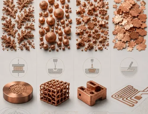
Silicon carbon composites: carbon matrices buffer volume change and improve conductivity. Common forms include amorphous carbon coatings, graphene-based frameworks, and nanotube networks.
-
Nanostructuring: nanoparticles, nanowires, and porous networks reduce absolute strain per particle and shorten diffusion paths.
-
Void-engineered structures: porous and yolk-shell structures internalize expansion, so external electrode dimensions change less.
-
Binder upgrades: elastic, adhesive binder systems improve mechanical integrity during swelling cycles.
A practical connectivity upgrade is the use of single-wall carbon nanotubes at low loadings, often around 0.05 to 0.5 wt%, to form a flexible 3D conductive network. Compared with carbon black, this network can bend and recover more effectively as the silicon expands and contracts.
Electrolyte and SEI strategies
Electrolyte additives can promote a more flexible, stable SEI. Fluoroethylene carbonate is a well-known example, although performance depends on the full electrolyte system and operating window. The core goal is to reduce repeated SEI rupture and slow impedance growth.
Process and manufacturing strategies
-
Architecture choice and scaling: composite structures can be produced via routes such as CVD, solid phase synthesis, mechanical alloying, or electrospinning, each with cost and throughput trade-offs.
-
Prelithiation: first cycle lithium loss can be so large that prelithiation becomes non-negotiable for many high silicon systems. Methods include stabilized lithium metal powder and sacrificial lithium salts. Scale-up requires tight control to avoid lithium plating or non-uniform lithium distribution.
-
Calendering control: excessive pressure can destroy expansion buffering structures, while insufficient pressure increases resistivity and lowers energy density.
-
Formation optimization: formation becomes more sensitive because SEI formation is both more extensive and more failure-prone. Gas management and yield control matter.
Emerging techniques can help in specific cases. Laser structuring can create microchannels that improve ion access and reduce stress concentration. Some solid-state approaches may also help because solid electrolytes can offer higher mechanical constraint and eliminate flammable liquids. However, many solid electrolytes still suffer from cracking and interfacial impedance growth under repeated silicon expansion, so this remains an active development area rather than a solved phone manufacturing solution.
How silicon-carbon batteries compare to other phone battery technologies
Silicon carbon anodes can increase energy density and enable faster charging compared with graphite-based lithium-ion and lithium polymer systems. The trade-off is reduced cycle life margin, more swelling risk, and a narrower safe operating window.
Graphite anodes offer stable, predictable performance and mature manufacturing. That is why they remain the default for consumer phones. Lithium iron phosphate offers strong safety and long cycle life at lower energy density, which limits its fit for thin phone designs.
At the manufacturing level, graphite uses well-understood slurry and coating processes. Silicon carbon introduces new complexities:
-
Reactive nano silicon can cause slurry instability and gas evolution during mixing.
-
Coating uniformity can suffer if rheology shifts mid-run.
-
Calendering is more delicate because it can collapse structures designed to buffer expansion.
-
Formation can become more lossy and more variable.
Some manufacturers use low silicon blends for incremental gains while avoiding high expansion regimes. High silicon content materials can show strong cycle performance under defined test windows, but those results need phone-relevant context. Real consumer duty cycles, thermal environment, and charging habits can shift the degradation profile.
What engineers ask when qualifying silicon carbon technology for phones
Engineers move quickly from “can it work” to “can we build it with yield and warranty safety.”
Typical gatekeeping questions include:
-
What silicon fraction meets the target cycle life and swelling limits for our phone design?
-
What degradation pattern appears under our charging profile, temperature range, and state of charge window?
-
What is the true cost and yield of the composite architecture at ton scale?
-
How do we prevent gas evolution in water-based slurry production?
-
What calendering pressure window preserves structure while meeting resistivity and density targets?
-
Can we integrate prelithiation into existing formation lines, and what is the throughput penalty?
-
How do we standardize incoming QC for silicon carbon composites and ensure batch-to-battery consistency?
-
What BMS controls are needed to manage unique aging and swelling signatures?
These questions determine whether the technology transitions from promising samples to a viable phone product.
Conclusion
Silicon-carbon battery issues are not mysterious. Expansion drives a cascade: mechanical damage, SEI instability, impedance rise, and swelling. The qualification path is also clear. You must tie the mechanism to measurement, then enforce decision rules that match phone lifetime, swelling tolerance, safety margins, and production yield. When the system meets those thresholds under phone-relevant duty cycles, silicon carbon becomes a credible phone technology. Until then, low silicon blends and carefully bounded charging windows remain the practical bridge.


