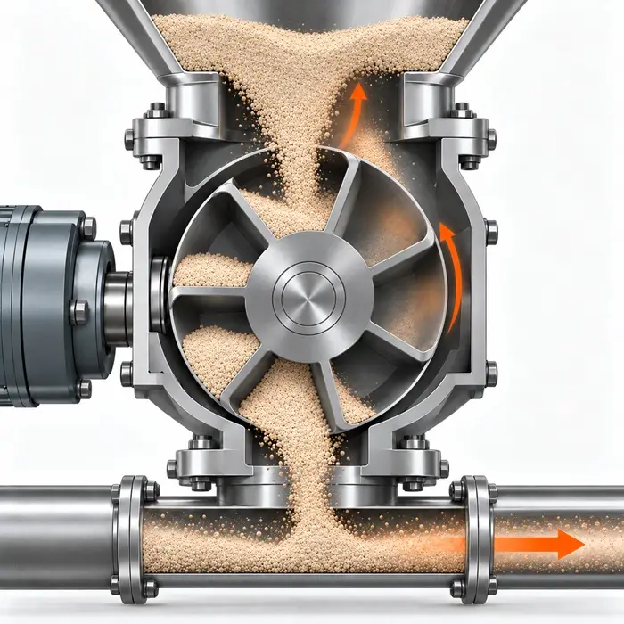
A plant switches to a finer mineral grade. The rotary airlock feeding its positive-pressure conveying line still turns at 20 rpm, but throughput falls from 23.0 to 16.8 kg/min. The drive shows no signs of overload, and there is nothing to suggest the rotor is binding.
Wear is one possibility, but the material change raises another: perhaps the valve is no longer filling as effectively. Fine powder may respond differently to the air returning from the conveying line, even when the valve itself has not changed.
Before taking the rotor apart, there is a more useful question to answer. How much powder does each revolution actually deliver?
Start With What Each Revolution Delivers
A catch test or reliable downstream weighing system will establish the actual mass flow. Dividing that result by the measured rotor speed gives the mass transferred per revolution.
In our example, the previous grade delivered 1.15 kg per revolution (23.0 ÷ 20). The finer grade delivers just 0.84 kg (16.8 ÷ 20), a reduction of almost 27%. The rotor has not slowed down; it is transporting less material each time it turns.
We can put those figures into context using the valve’s theoretical capacity. Suppose its total swept pocket volume is 2 L per revolution and, for this illustrative comparison, both grades have a bulk density of 0.7 kg/L. The theoretical capacity is then 1.4 kg per revolution.
That gives approximately 82% for the original grade and 60% for the replacement. Neither figure is inherently good or bad. Rotary valves often operate below their theoretical displacement, and the expected efficiency depends on the material, pressure conditions, and valve design.
The change is what matters. Real powder grades may also have different bulk densities, which must be measured rather than assumed equal. The calculation also reflects material that remains inside the pockets during discharge, so it should not be mistaken for a direct measurement of inlet filling alone.
For this finer grade, the inlet is the logical place to start.
When Returning Air Interferes With Filling
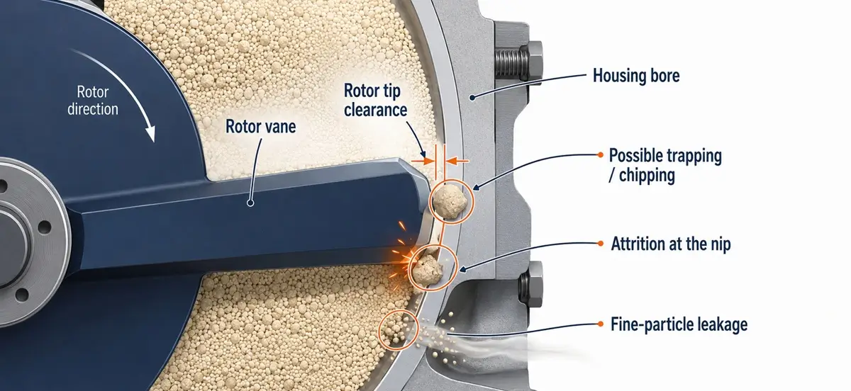
A rotary airlock transfers solids while maintaining a pressure difference between two parts of a process. Gas inevitably leaks through the small running clearances between the rotor and housing. Empty rotor pockets also carry pressurized gas back toward the inlet after discharging into the conveying line.
That returning air can oppose the incoming powder. A finer, readily aerated material may struggle to enter the pockets against the upward gas flow, leaving the valve turning normally but delivering less mass.
If a leakage-air vent is fitted, its line and filter are among the first things to inspect. A blockage can allow returning gas to interfere with filling rather than escaping through the intended route. Venting is not required in every installation, and its design must suit the material and pressure conditions.
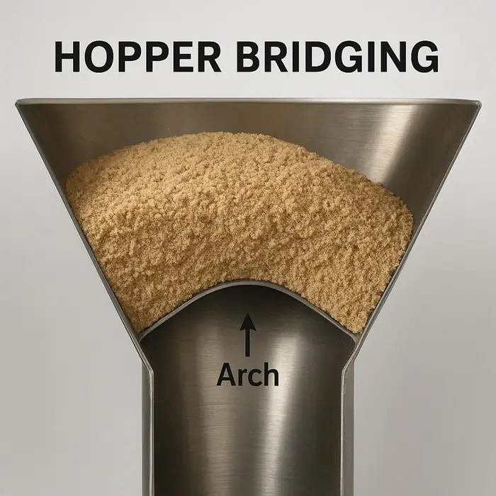
Air is not the only reason powder may fail to enter the valve. Cohesive material can form a stable bridge above the inlet, starving the rotor pockets even when the venting system is working properly. The mechanism is similar to hopper bridging, where powder strength and outlet geometry determine whether material continues to flow.
Increasing rotor speed is not necessarily the answer either. In the SHAPA practical guide to rotary valves, Ian Blackmore and Professor Mike Bradley discuss how filling efficiency depends on rotor speed, pressure differential, and the material being handled. More revolutions can mean less filling time, particularly when airflow already opposes the powder.
When the Valve Itself Is the Problem
If powder enters freely and the venting system is working, the next question is whether the pockets empty properly. Sticky material may adhere to their surfaces and remain there after discharge, leaving less room for fresh powder on the next revolution.
Wear tells a different story. Abrasive particles gradually remove material from rotor tips and housing surfaces, and solids entrained in high-velocity leakage air can contribute to erosion. Larger clearances allow more gas to bypass the rotor. However, leakage can also increase when the pressure differential rises, even if the clearances have not changed.
Rather than diagnosing wear from motor current, compare the operating pressure and measured clearances with the manufacturer’s specifications and earlier maintenance records. Hardened components, replaceable tips, or lower tip speed may be appropriate where wear is confirmed, but any modification must maintain capacity, sealing performance, and certified safety clearances. This is particularly important when the valve also provides explosion or flame isolation.
A genuine jam is more abrupt. Hard lumps, foreign objects, or oversized particles can become trapped as the rotor passes the inlet edge. The risk depends on their dimensions and the inlet geometry, not simply on the powder’s D90. Most powder travels inside the pockets, and a rare oversized object may barely register in a measured particle size distribution.
Amrit Agarwal, writing in Chemical Engineering in 2013, describes offset inlets and V-shaped inlet plows designed to reduce such entrapment.
Temperature can produce a similar stoppage without an obstructing particle. During startup with hot product, the rotor, which sits directly in the product stream, may heat and expand faster than the housing, which loses heat to its surroundings. The resulting reduction in running clearance can cause contact before temperatures stabilize.
What to Check First
A useful diagnosis combines the throughput measurement with observations made while the valve is running.
| What you observe | Where to investigate |
|---|---|
| Throughput drops, rotor turns normally | Mass per revolution, inlet flow, vent line and filter, pocket discharge |
| Leakage rises gradually | Pressure differential, rotor and housing clearances, abrasive wear |
| Motor overload or intermittent stall | Trapped lumps, deposits, foreign objects, thermal expansion |
| Performance changes with a new powder grade | Bulk density, aeration, cohesion, moisture |
| Material remains in rotor pockets | Adhesion, buildup, pocket geometry, discharge conditions |
Motor current and unusual noise can support the investigation, but neither identifies a failure mechanism on its own. Internal inspections require the equipment to be isolated and locked out, stored pressure released, and any material that could move secured.
Back at our mineral-processing plant, the fall from 1.15 to 0.84 kg per revolution is enough to justify checking the inlet and venting before replacing worn parts. If both are clear, the next question is whether powder remains in the pockets after discharge. Only then do clearance measurements become the more convincing route to an explanation.