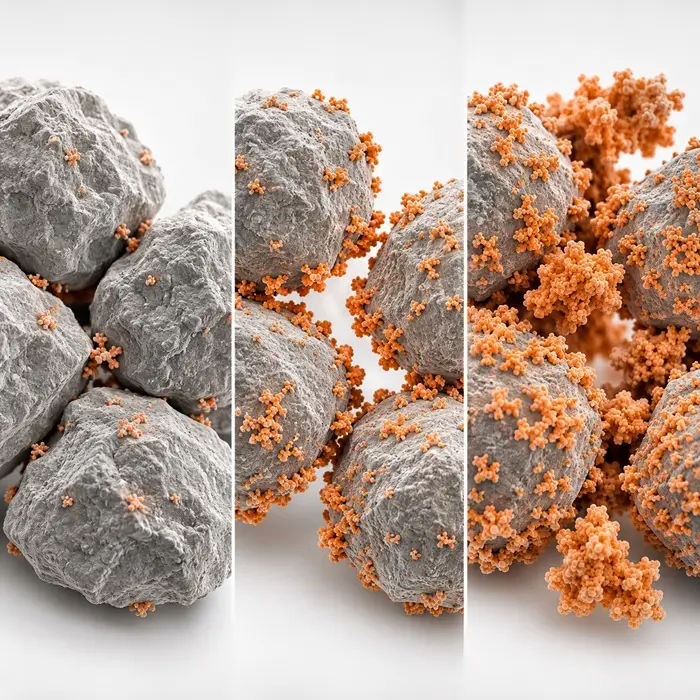

Lithium iron phosphate has moved well beyond its former position as a lower-cost alternative to nickel-rich battery chemistries. According to the International Energy Agency’s Global EV Outlook 2026, LFP accounted for more than 55% of electric vehicle batteries deployed worldwide in 2025 and over 90% of stationary battery storage installations.
Meeting that demand requires enormous quantities of cathode powder, manufactured to specifications that extend well beyond chemical composition. Particle size distribution, tap density, carbon content, surface area, moisture, and metallic contamination all affect whether an LFP powder can be processed consistently into electrodes.
The difficulty is that these properties are closely connected. Milling the precursor more finely may improve its reaction during calcination but also change the slurry’s behavior in the spray dryer. More intensive calcination can strengthen the resulting particles, only for the final milling stage to break them apart again. The powder leaving the production line reflects the accumulated effects of every operation, not simply the settings of the last machine.
From Iron Phosphate to Battery-Grade LFP
Much of today’s commercial LFP production, particularly in China, follows an iron phosphate-based route. Iron phosphate (FePO₄) is combined with a lithium source, commonly lithium carbonate (Li₂CO₃), and a carbon-containing additive before being converted into LiFePO₄ during thermal treatment.
The process typically passes through seven stages: iron phosphate precipitation; wet bead or sand milling to reduce precursor size and disperse the ingredients; spray-drying into composite granules; calcination in a controlled atmosphere; jet milling and air classification; magnetic separation; and blending, quality control, and packaging.
Other synthesis routes exist, including processes starting from iron oxides. These differ in precursor chemistry and reaction conditions, but face many of the same powder-engineering questions. The particle dimensions established by wet milling are not necessarily those measured in the final product. Spray-drying creates larger secondary structures, calcination changes their internal strength and morphology, and final milling determines how much of that structure remains.
Wet Bead Milling: Where Particle Size Control Begins
Long before the LFP reaches a jet mill, its precursor particles have already undergone substantial size reduction. In the iron phosphate route, FePO₄, Li₂CO₃, and a carbon source, often glucose or another suitable organic compound, are dispersed in a liquid medium. The mixture passes through wet bead mills, sometimes in several stages, until the required fineness and dispersion are achieved.
Industrial systems can reduce precursor particles into the hundreds-of-nanometers range. The intended distribution depends on the formulation and the calcination process that follows. A finer precursor generally offers shorter diffusion distances and more intimate contact between reactants, which can help achieve uniform conversion during thermal treatment.
There is a limit to how far it pays to take that reduction. Smaller particles create more surface area, and the slurry may become increasingly difficult to handle as viscosity changes. Milling energy rises, equipment wear becomes more important, and poorly controlled dispersion can cause problems when the slurry reaches the dryer.
Bead size, agitator speed, residence time, solids loading, and the number of milling passes all influence the result. But particle size alone does not tell the whole story. Two slurries with similar median sizes may behave differently if one contains a larger coarse fraction or more strongly agglomerated material. For that reason, a wet-milling specification needs to cover more than D50.
Spray-Drying: Building the Particles That Enter the Kiln
The milled slurry now has to be converted into a dry, reasonably uniform feed for calcination. Spray-drying achieves this by atomizing the slurry into droplets, which lose moisture as they travel through the drying chamber. Each droplet can form a composite granule containing the different precursor components, held together in a secondary structure.
Near-spherical granules are attractive because they can pack efficiently and feed more consistently than irregular agglomerates. Yet the external shape can be misleading. Depending on how a droplet dries, the resulting particle may be dense, porous, or partly hollow. Two apparently similar granules may therefore respond quite differently to calcination and subsequent milling.
A study published in Materials Letters, High tap-density and high performance LiFePO₄/C cathode material synthesized by the combined sol spray-drying and liquid nitrogen quenching method, reported spherical secondary particles approximately 0.1–6 µm in size and a tap density reaching 1.53 g/cm³. The researchers achieved this through a combined spray-drying, thermal treatment, and quenching route.
That result demonstrates what controlled secondary particle formation can contribute to packing density. In a production plant, the spray dryer also has to deliver granules that will react uniformly in the kiln and remain suitable for final size reduction. A particularly dense granule is not necessarily an advantage if it becomes a hard agglomerate that requires excessive milling to break apart. See modern spray-drying technology.
Calcination: More Than Forming the Right Crystal Structure
Once the precursor granules have been formed, calcination converts the mixture into crystalline LFP. In commercial iron phosphate-based production, this commonly takes place in a continuously operated roller-hearth kiln under nitrogen. Temperatures around 700–780°C provide an indicative commercial operating window, although the synthesis literature describes a broader range of approximately 600–800°C.
Controlling the atmosphere is essential. Iron in LFP is predominantly present as Fe²⁺, and unwanted oxygen exposure during synthesis can encourage oxidation and the formation of impurity phases. The atmosphere must support the required chemical reactions while maintaining suitable conditions for carbon formation.
Carbon is particularly important because pristine LFP is a poor electronic conductor. Its intrinsic electronic conductivity is commonly reported around 10⁻⁹–10⁻¹⁰ S/cm, with electrons transported through a small-polaron hopping mechanism. Lithium-ion transport occurs predominantly through one-dimensional channels along the crystallographic [010] direction. A <a href=”https://pmc.ncbi.nlm.nih.gov/articles/PMC11596918/”>review of LFP conductivity-enhancement strategies</a> explains why carbon coating and primary crystallite-size control matter.
The carbon source serves another purpose during synthesis. Besides forming conductive carbon around the LFP particles, it can restrict crystal growth during calcination. This helps maintain smaller crystallites and shorter lithium-ion diffusion distances. How much carbon is present, where it is distributed, and how it behaves during heating can therefore affect both electrical performance and particle morphology.
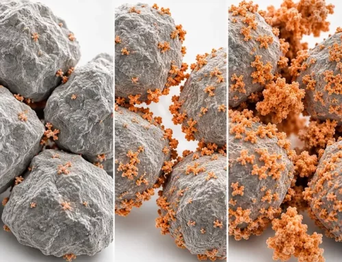
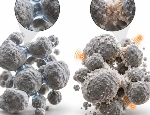
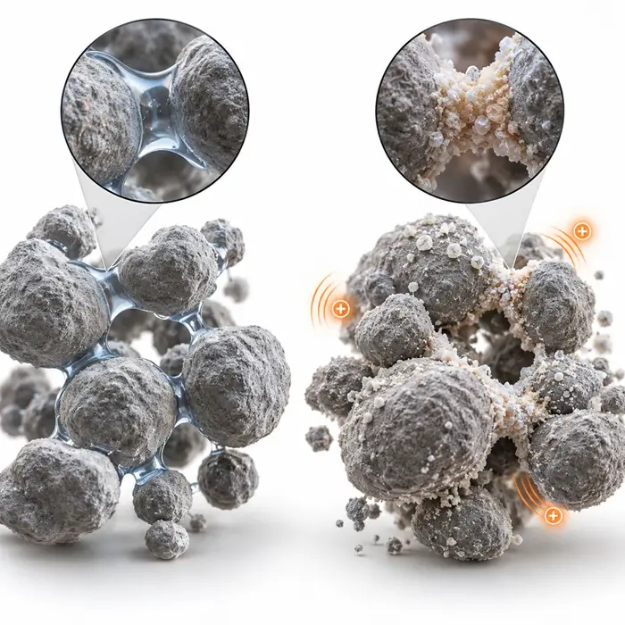
Meanwhile, heat promotes diffusion and neck formation between neighboring crystallites. Some consolidation is useful, but as sintering progresses, particles may become strongly bonded. What entered the kiln as discrete granules can leave as a much harder agglomerated mass. Calcination must proceed far enough to form the desired phase and carbon structure without causing unnecessary grain growth or producing material that is excessively difficult to mill.
Jet Milling and Classification: Finer Is Not Always Better
The calcined material often needs further size reduction before it can meet the specification for a finished cathode powder. Hard agglomerates must be broken down, and the product may need classification to control oversized particles and the distribution of fines. Jet milling uses high-velocity gas to accelerate particles and generate collisions. Gas pressure, feed rate, particle strength, and classifier settings determine how aggressively the material is processed. See jet milling and process control.
The immediate result may look satisfactory on a particle size report. D50 decreases, and classification removes material above the specified cut size. But a reduction in median size does not reveal what happened to the secondary particle structure.
In the Journal of Electrochemistry, Effects of Jet Milling and Classifying Process on the Performance of LiFePO₄/C in Full Batteries reported that milling and classification fractured spherical secondary particles, reducing tap density and carbon content. Although several battery-performance measurements changed little, the material retaining its spherical structure performed better in low-temperature discharge capacity retention and high-temperature cycling.
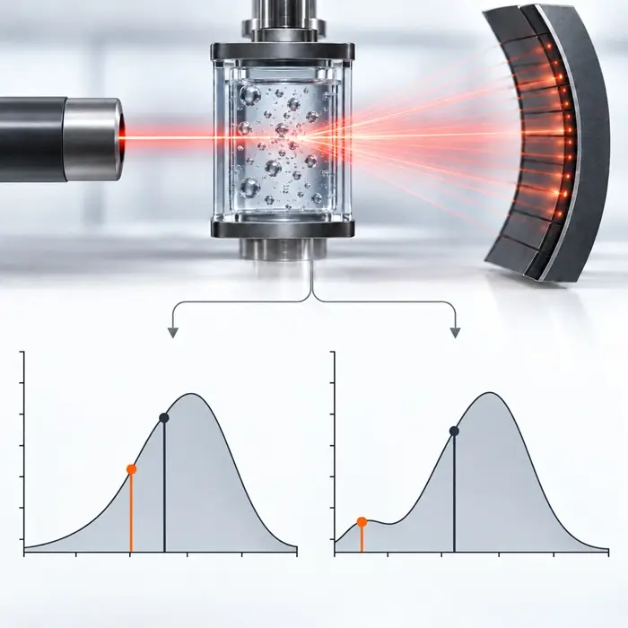
Breaking up oversized agglomerates may be necessary, but continuing to mill once the required distribution is reached can increase fines, change surface area, and reduce packing efficiency. A final specification should consider D10, D50, and D90 together, along with fines and oversize fractions. Our guide to interpreting particle size distributions explains why the median alone can conceal important differences.
What Does a Commercial LFP Powder Specification Look Like?
Commercial LFP grades differ according to application and electrode manufacturing requirements. Nevertheless, published supplier specifications provide a useful indication of the property ranges producers work toward.
| Property | Indicative commercial range |
|---|---|
| Particle size, D50 | 1–3 µm for many mainstream fine-powder grades |
| Tap density | 0.7–1.5 g/cm³ across published grades |
| Powder compaction density | 2.3–2.5 g/cm³ for conventional grades |
| High-compaction powder density | 2.6 g/cm³ and above for specialized grades |
| Carbon content | 1–2.5 wt% |
| BET specific surface area | 9–20 m²/g |
| Moisture content | ≤1,000 ppm; measured values often in the hundreds of ppm |
| Magnetic impurities | Frequently ≤1 ppm for specified magnetic contaminants |
Published product data put these figures into context. Xnergy’s DF-5 LFP product sheet reports a D50 of 1.03 µm, tap density of 1.05 g/cm³, compaction density of 2.48 g/cm³, BET surface area of 10.31 m²/g, and moisture content of 300.5 ppm. Another Xnergy LFP grade specifies moisture below 1,000 ppm and magnetic impurities below 1 ppm. An ACEM Energy LFP specification also lists a moisture limit of 1,000 ppm and reports a measured value of 764 ppm.
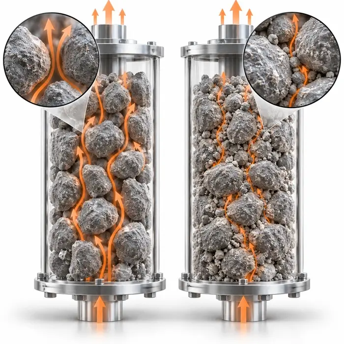
Tap density describes the mass of powder occupying a given volume after a specified tapping procedure. It differs from loose bulk density and from powder compaction density, which is obtained at much higher pressure. A powder with good tap density will not necessarily produce the densest electrode, because particle morphology, formulation, carbon content, and consolidation conditions also contribute.
In an Ionics study published on January 12, 2026, Nb, Ti, and V co-doping was combined with non-uniform particle size grading. The researchers reported a powder compaction density of 2.72 g/cm³ under 226 MPa, with smaller particles helping fill the spaces between larger ones. Deliberately combining particle sizes can improve packing, though it may also affect cohesion, surface area, and electrode processing.
Magnetic Separation: Keeping Metallic Contamination Out of the Final Powder
By the time LFP has passed through wet milling, calcination, jet milling, and several transfer operations, it has encountered numerous opportunities for contamination. Grinding media, contact surfaces, and worn equipment components can introduce metallic particles even when the incoming raw materials were within specification.
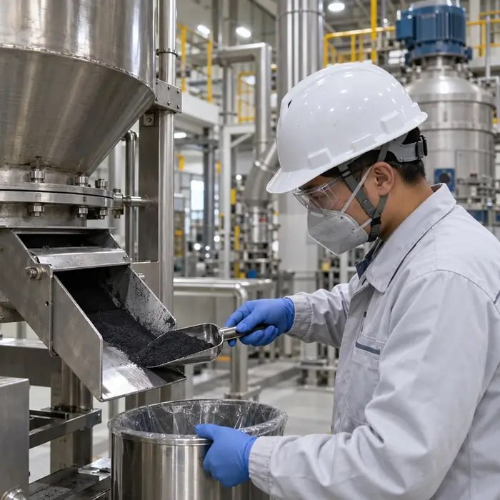
Battery-grade LFP therefore undergoes magnetic separation before final packaging. Some commercial specifications set magnetic impurity limits below 1 ppm. Removing those particles is not simply a matter of installing a sufficiently strong magnet: the separator must process a continuous stream of fine powder and bring susceptible contaminants close enough to its collection surfaces to be captured.
Cohesive powder presents a particular difficulty. Agglomeration may shield metallic particles, while uneven flow through the separator can leave part of the stream inadequately treated. Contamination control must also extend upstream. If grinding media or equipment components are wearing excessively, magnetic separation may capture some particles without addressing their source, and it cannot remove contaminants that are not sufficiently magnetic.
Flowability, Surface Area, and Moisture: What Happens After Powder Production?
The powder may meet its particle size, density, and purity specifications but still has to perform in electrode manufacturing. In conventional wet processing, LFP is mixed with conductive additives, binder, and solvent to form a slurry. Particle size distribution, carbon characteristics, surface area, and moisture influence how readily it disperses and how the slurry behaves. In dry electrode manufacturing, the lack of conventional liquid slurry places more emphasis on powder mixing, cohesion, feeding, and mechanical consolidation.
Flowability Is Not the Same as Tap Density
Tap density is a convenient quality indicator, but it cannot describe powder behavior under every handling condition. Two LFP powders with similar tap densities may have different cohesive strengths, particle shapes, or aeration responses. Loose bulk density and the Hausner ratio add information for routine batch comparisons. See why bulk density alone can mislead powder analysis.
For hopper and feeder design, shear testing is generally more informative because it measures powder strength under defined consolidation conditions. Our comparison of Jenike shear cells and ring shear testers explains the difference. Dynamic and aerated powder testing can help where materials experience changing aeration or low-stress handling.
Fine Particles Also Mean More Dust
The fine fraction affects more than the PSD specification. It can increase dust generation during pneumatic transfer, hopper filling, and packaging, while changing the powder’s response to electrostatic charging. A rise in dustiness after a milling adjustment is worth investigating alongside fines content and secondary particle morphology. Fine carbon-containing powders should be assessed for material-specific dust hazards rather than relying on composition alone. See <a href=”https://powdertechnology.info/managing-powder-dustiness-in-industrial-plants/”>managing powder dustiness in industrial plants</a>.
A Little Moisture Can Have a Significant Effect
Moisture is easy to overlook when particle size and tap density are within specification. Commercial LFP grades commonly carry moisture limits of 1,000 ppm or less, with Karl Fischer methods used to determine water content at these concentrations.
Conventional cathode formulations often use N-methyl-2-pyrrolidone (NMP) as solvent and polyvinylidene fluoride (PVDF) as binder. Water introduced with the powder can alter particle and binder interactions, making slurry viscosity and dispersion less predictable. Under susceptible formulation conditions, moisture may contribute to instability or gelation, although binder-mediated flocculation and other effects can produce similar symptoms. Research on the rheology and stability of NMP-based cathode slurries illustrates these interactions.
Moisture control cannot stop when finished powder passes its release test. Exposure during storage, transfer, or handling can change its condition before mixing. Packaging integrity and environmental control therefore deserve the same attention as measurement. See moisture control for powders.
Tracing a Powder Problem Back to the Process
A problem appearing at the end of the line may have originated several operations earlier. A lower tap density may follow excessive jet milling, for example, but the underlying change could begin with the spray-dried granule structure. Comparing an affected batch with a known reference helps identify which characteristics changed before adjusting equipment.
| Observed symptom | First measurement to check | Possible process cause |
|---|---|---|
| Precursor slurry harder to process | Wet-milling PSD and slurry viscosity | Milling intensity, solids loading, or dispersion conditions |
| Spray-dried granules irregular | Granule morphology and moisture | Atomization or drying-condition changes |
| Calcined product harder to mill | Agglomerate strength and morphology | Increased sintering or thermal-treatment changes |
| Final D50 or D90 increases | Complete PSD and classifier performance | Reduced milling effectiveness or classifier drift |
| Tap density decreases | PSD and secondary particle morphology | Granule breakage or altered packing |
| BET surface area increases | Fine fraction, morphology, and BET | Additional fines or changed thermal processing |
| Magnetic impurities increase | Contaminant analysis and separator performance | Equipment wear or ineffective magnetic separation |
| Slurry viscosity increases | Moisture, BET, PSD, and dispersion quality | Powder surface changes, fines, or formulation interactions |
Consider a batch with lower tap density but an unchanged D50. Looking only at the median might suggest stable milling. Microscopy and a closer examination of the fine fraction, however, could reveal fractured secondary particles without much movement in the median.
A similar problem arises when slurry viscosity increases. Changing the binder or solvent ratio may seem the quickest remedy, but the cause could be higher BET surface area, additional fines, or moisture picked up during storage. Linking measurements to manufacturing stages allows engineers to work backward through the process and test the most plausible explanation.
FAQ: LFP Cathode Powder Production
Technical Basis / Sources
IEA, Global EV Outlook 2026, Electric Vehicle Batteries.
Review of LiFePO₄ conductivity-enhancement strategies.
Materials Letters: Spray-drying and liquid nitrogen quenching of LiFePO₄/C.
Journal of Electrochemistry: Effects of jet milling and classifying LiFePO₄/C.
Ionics: High-density LFP with co-doping and non-uniform particle grading (2026).
Xnergy DF-5 product specifications; Xnergy XDNP01-2 product specifications; ACEM Energy LFP specifications.