
Process & equipment
Storage & Discharge
Define the flow pattern, outlet, and discharge interface together
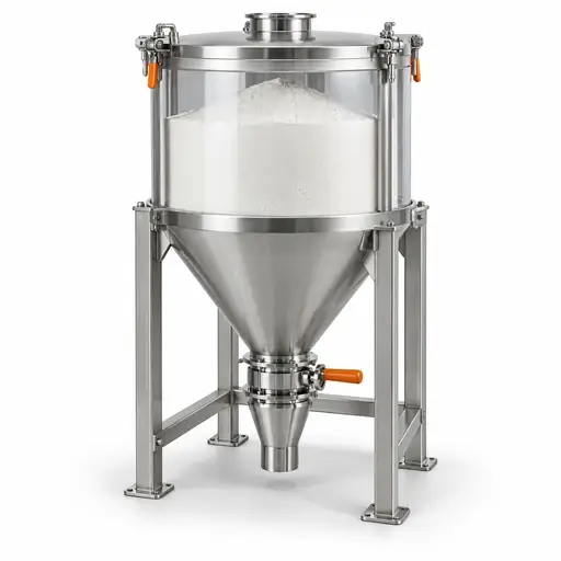
Start with the inventory, discharge duty, and product condition the process must preserve. Use representative powder data to assess hopper geometry, wall surfaces, outlet dimensions, and the equipment that withdraws material.
Process & equipment
Storage & Discharge
Define the flow pattern, outlet, and discharge interface together
Start with the inventory, discharge duty, and product condition the process must preserve. Use representative powder data to assess hopper geometry, wall surfaces, outlet dimensions, and the equipment that withdraws material.




Jump to
Jump directly to the engineering decision you need to resolve, or work through the sections to connect process requirements, powder data, equipment choices, and verification.
Key takeaway
Establish the discharge requirement before choosing the hardware
Choose storage and discharge arrangements around the required flow pattern, usable inventory, discharge rate, storage duration, and acceptable product variation. Use suitable strength, wall-friction, density, and, where relevant, permeability data to support the design. Confirm that the outlet and withdrawal equipment work together, then verify restart, drawdown, and refill conditions with representative material. A hopper angle, a nominal outlet diameter, or a discharge aid alone is not a complete specification.
Start with the requirement
Define what the vessel must deliver
Write the duty in terms of usable inventory and delivered material, not only nominal vessel volume. Agree which operating cases must pass acceptance before equipment is selected.
Powder constraints
Use only the properties that affect this duty
Identify the powder properties that constrain storage and discharge, then connect each constraint to the measurement needed for design.
Choose by application question
Start with the unresolved engineering decision
Start with the unresolved engineering question, then follow the relevant decision route and supporting evidence.
Which flow pattern does the application require?
Compare the consequences of active and retained inventory.
Review the decisionWhat determines the outlet size?
Separate obstruction resistance from the required delivery rate.
Review the decisionWhich wall material and finish should be tested?
Evaluate candidate surfaces under representative conditions.
Review the decisionWhen is a discharge aid appropriate?
Identify the intended action and the evidence needed to justify it.
Review the decisionHow should the hopper and feeder work together?
Check withdrawal across the intended active outlet.
Review the decisionHow can drawdown preserve product consistency?
Plan discharge sampling and limits on material variation.
Review the decisionEquipment principles
Choose the flow pattern the duty requires
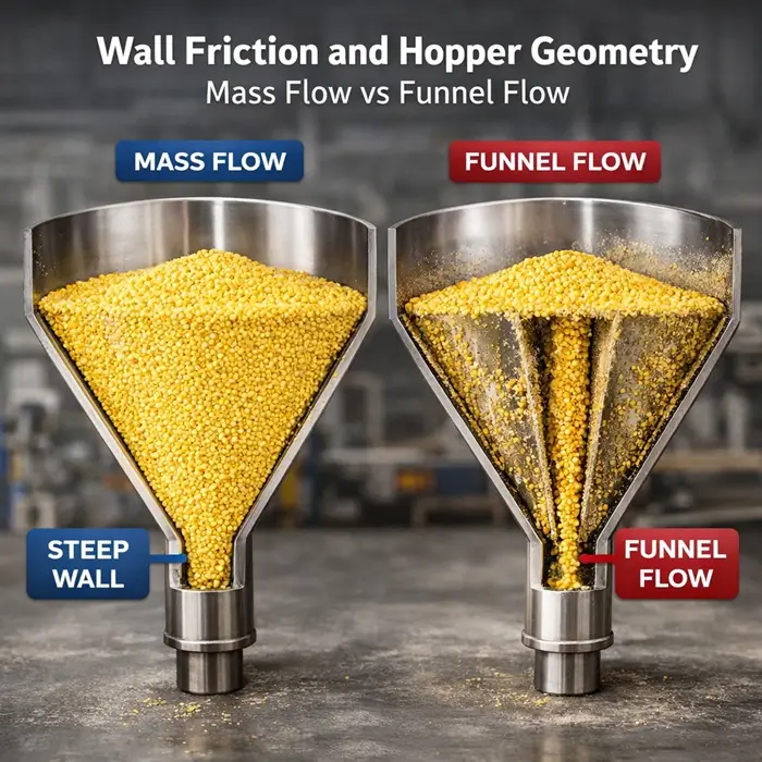
In mass flow, the bed moves throughout during withdrawal. Funnel flow retains regions outside an active channel. Assess whether retained inventory, broad residence times, and drawdown variation are acceptable for this product. Mass flow is not a guarantee of identical particle residence times or a substitute for a blend-uniformity check.
Use the selected geometry and relevant friction data to assess wall slope. Do not infer a hopper angle from angle of repose. State whether angles are measured from vertical or horizontal. Schulze explains the flow-pattern and geometry framework.
Outlet decision
Check both obstruction resistance and required rate
Separate cohesive arching, coarse-particle interlocking, and potential stable ratholes in a funnel-flow arrangement. Use an appropriate design calculation and representative material data rather than a fixed multiple of average particle size.
An opening that avoids obstruction may still fail the delivery-rate requirement. Fine-powder rate assessment must consider gas movement through the bed. Jenike & Johanson discusses permeability-related rate limits and flooding.
Decision output: a justified outlet shape and critical dimension, checked against the specified rate and downstream interface. The material flow function and the geometry-dependent hopper flow factor are different quantities; a single flowability index is not an outlet calculation.
Wall-surface decision
Test the surface the powder will actually contact
Compare candidate coupons at relevant loads and conditions. Include joints, finish direction, expected wear, deposits, or cleaning effects when they could change the contact. A material name or surface-roughness number alone is not a measured powder-wall friction relationship.
Evaluate liner thickness, attachment details, transitions, cleaning, chemical compatibility, and wear life alongside the friction result. An inward step or exposed fixing can compromise an otherwise suitable surface.
Decision output: a qualified surface specification and geometry assessment, with an inspection or replacement criterion. Review wall-friction testing.
Discharge-aid decision
Define the action before selecting the aid
A vibrator, agitator, live bottom, insert, and aeration system act differently. State whether the aim is mobilization at a wall, mechanical extraction, stress redistribution, or a controlled change in gas-solid behavior. Match the proposed action to the limiting operating case.
Evaluate the tradeoff through a planned trial: product damage, compaction, gas loading, dust, fatigue, cleanability, or added obstructions may matter. An aid is not evidence that the passive geometry or withdrawal interface is adequate.
Decision output: a defined activation sequence, operating limits, failure response, and trial evidence. Structural loads from inserts or mechanical aids require separate assessment.
Hopper and feeder
Preserve the intended active outlet
Specify the feeder inlet and hopper outlet together. For a long slot, verify where material enters the withdrawal device along its length. A nominally open slot does not prove active extraction everywhere.
A screw or belt arrangement may require increasing available conveying capacity along the inlet. The exact profile depends on the material and geometry; the diagram represents the principle only. See the integrated storage-and-feeding design guidance.
Decision output: an interface drawing, extraction assessment, startup-load check, and defined rate-control boundary. Continue to Feeding & Dosing for feeder accuracy and control selection.
Product-consistency decision
Specify what may change through the discharge cycle
Set acceptance limits for the characteristics that matter downstream: composition, particle-size distribution, bulk density, temperature, or another defined attribute. Sample by discharged mass or operating phase, not only at the beginning and end.
Include the filling arrangement and transition into the receiver. A satisfactory average sample can conceal short-lived departures. Treat retained inventory and incomplete cleanout as explicit acceptance questions.
Decision output: a drawdown sampling plan and an agreed variation limit across normal operation and restart. Review segregation mechanisms.
Selection comparison
Compare design choices and their boundaries
Combine compatible design choices to meet the storage and discharge duty.
Principle or choice | Best fit | Critical powder inputs | Strength | Limitation | Scale-up / integration |
|---|---|---|---|---|---|
| Mass-flow gravity arrangement | Duty requiring movement throughout the bed | Strength, wall friction, density; gas behavior where relevant | Limits stagnant inventory when correctly implemented | Requires suitable geometry and full-outlet withdrawal | Check available headroom, outlet, feeder and as-built surface together |
| Funnel-flow arrangement | Duty that tolerates retained zones and its residence pattern | Strength after storage, particle distribution and drawdown behavior | May fit an existing vessel or spatial constraint | Retained material and nonuniform drawdown need explicit assessment | Verify usable capacity and emptying strategy; do not assume nominal volume is active |
| Conical or transition hopper | Compact outlet interface or geometry compatible with the selected feeder | Friction and strength data for the chosen geometry | Can connect storage to a compact discharge interface | No universal wall angle or outlet size | Assess transitions and feeder opening, including any ledges |
| Wedge hopper with slot outlet | Elongated extraction interface | Friction, strength, bulk density and slot extraction behavior | Provides a route to a long active outlet | The slot must remain effective along its length | Specify feeder inlet, extraction profile and supports together |
| Liner or surface modification | A demonstrated wall-interaction constraint | Wall tests on representative candidate surfaces | Changes a boundary without necessarily replacing the vessel | Wear, installation steps and cleaning may change performance | Reassess geometry and local dimensions after installation |
| Engineered insert | A justified change to internal stress or movement | Material tests and validated design analysis | May offer a retrofit route in a constrained vessel | Adds loads, contact surfaces and possible obstructions | Check attachments, access, cleanout and structural consequences |
| Mechanical extraction or aid | Duty requiring a defined imposed action | Strength, fragility, density and equipment trial data | Provides controlled mechanical action | Can add damage, compaction, wear and maintenance | Specify duty cycle, drive loads, interlocks and product limits |
| Aeration or gas-assisted arrangement | Fine-powder duty supported by gas-solid evidence | Permeability, aeration and deaeration response | Can modify a limiting gas-solid condition | May upset rate control or increase dust and vent demand | Coordinate gas quality, dosing, venting and downstream pressure |
Operating window
Qualify the conditions that keep the selection valid
Qualify operating ranges through material testing, design calculations, and trials.
Variable | Why it matters | What must be established |
|---|---|---|
| Storage duration and restart | Strength or adhesion after a loaded pause may differ | Agree the maximum pause and restart test; qualify more than continuous running |
| Fill range and refill sequence | Material state and inlet conditions vary across the cycle | Verify low, normal and high inventory and simultaneous fill/discharge if used |
| Moisture and temperature | The operating material can differ from the lab sample | Set the qualified range, conditioning history and response to excursions |
| Discharge rate | Receiver demand and available gravity supply must agree | Verify sustained minimum/normal/peak delivery and transient overshoot limits |
| Wall and liner condition | Service can change the contact boundary | Define inspection condition, acceptable buildup and replacement triggers |
| Gas pressure and vent performance | Air exchange affects the stored and discharged powder | Check filling surges, vent loading, pressure differences and post-fill behavior |
| Aid activation | An intermittent intervention changes the process state | Define triggers, duration, permitted product effects and stop conditions |
Data needed before design or scale-up
Connect each measurement to a design decision
Request decision-specific measurements. ASTM D6128 and D6773 define shear-test procedures, not complete hopper or feeder designs.
Engineering decision | Evidence needed | Relevant conditions | What it supports | What remains to verify |
|---|---|---|---|---|
| Hopper slope and wall choice | Wall-friction data and relevant internal-friction data | Candidate surfaces; relevant stresses, moisture, temperature and contact time | Geometry assessment with a suitable hopper design model | Design margin, joins, fabrication tolerance and service surface condition |
| Outlet resistance to cohesive obstruction | Flow function / shear testing, time consolidation where relevant, and bulk density | Representative lots, storage time and stress range; cell suited to particles | Input to a justified outlet and, where relevant, rathole assessment | Selected model, geometry, coarse-particle passage and actual withdrawal |
| Working inventory and loaded interface | Bulk density and packing response | As-filled, settled and consolidated states appropriate to duty | Mass-volume envelope and inputs to further load assessment | Vessel load cases, supports, feeder startup torque and usable capacity |
| Fine-powder discharge and gas assistance | Permeability, aeration and deaeration | Relevant bed state, stress and gas conditions | Input to gas-solid rate assessment and trial planning | Full system pressure, vent behavior, geometry and rate control |
| Product consistency and damage | PSD / morphology plus appropriate composition or integrity measurements | Representative feed and samples through filling and drawdown | Comparison of product condition and variability | Acceptance against the downstream product requirement; sampling adequacy |
| Feeder withdrawal and restart | Equipment trial with defined material state and operating sequence | Relevant inlet geometry, inventory and standstill; representative limiting lots | Evidence of extraction pattern and delivery performance | Scale effects, full equipment loads and site integration |
Verification and acceptance
Agree what success looks like before the trial
Write numerical project-specific acceptance limits before testing. Record the tested material envelope, equipment configuration, duration, sampling method, and deviations. Do not adopt the first successful run as the operating specification.
Upstream and downstream integration
Specify the interfaces as part of the equipment
Mark the ownership of every interface on the design drawing. Include operating and stopped conditions so one unit does not depend on an unstated assumption about its neighbor.
When a problem is already occurring
Use the diagnostic route before selecting a retrofit
For an installed system, use Poor Flow and Discharge, Caking and Agglomeration, or Segregation and Blend Inconsistency.
Return here once the evidence identifies the engineering decision to resolve.
Go deeper
Published technical articles
Continue into the specific property, test-selection, and interface questions behind this guide.


Technical FAQ
Equipment-selection questions
Use these boundaries when preparing a specification or reviewing a proposed change.
Technical basis
Sources and engineering scope
This is a selection and evidence guide, not a dimensional design calculation. Use complete applicable methods and the project-specific structural, mechanical, pressure and safety requirements. Manufacturer engineering references support the stated principles, not a vendor ranking.
- Dietmar Schulze: Storage of Powders and Bulk Solids in Silos: flow patterns and the flow-property basis of hopper geometry.
- ASTM D6128-22: Jenike shear-test procedure; use the apparatus scope and relevant sample conditions.
- ASTM D6773-22: Schulze ring shear-test procedure; an apparatus-specific measurement route.
- Jenike & Johanson: integrated storage and feeding: outlet and feeder interface principles.
- Jenike & Johanson: discharge-rate limitations: gas movement and fine-powder discharge.
- Jenike & Johanson: conceptual and functional engineering: the scope of geometry, capacity, outlet and feeder decisions.
Need the material data behind the design decision?
Define the storage duty, material range, candidate surfaces and required discharge performance before commissioning characterization. Delft Solids Solutions can discuss the relevant testing scope. Contact the laboratory with the application question and available sample information; agree separately who will perform the equipment design and scale-up assessment.