
Process & Equipment
Feeding & Dosing
Match the feed system to the material and delivery requirement
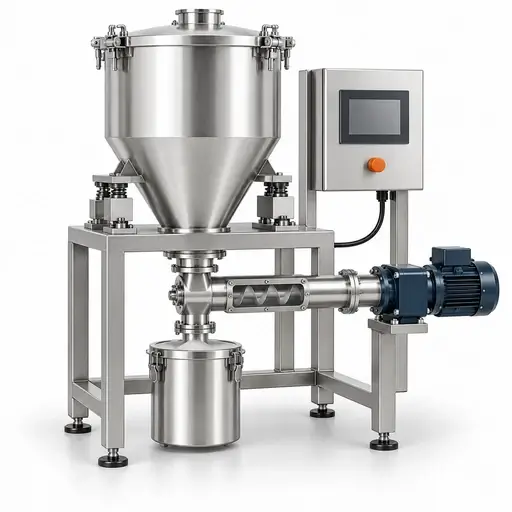
Specify the mass rate or dose, the time scale that matters, and the powder conditions the feeder must handle. Compare feeding principles, control modes, refill strategies, and installation requirements against measured performance.
Process & Equipment
Feeding & Dosing
Match the feed system to the material
and delivery requirement
Specify the mass rate or dose, the time scale that matters, and the powder conditions
the feeder must handle. Compare feeding principles, control modes, refill strategies,
and installation requirements against measured performance.




Jump to
Jump to a specific engineering decision, or follow the sections from process requirements through equipment selection and verification.
Key Takeaway
Specify delivered performance
Select a feeder around the required mass delivery and the time interval over which it must be achieved. Powder flow, density, aeration, and particle damage influence the metering mechanism; weighing and control determine how delivery is measured and corrected. Qualify the complete system across low and high rates, refill, restart, and realistic material variation. A nominal capacity or a single accuracy percentage does not establish suitability.
Start with the requirement
Define the duty before choosing the feeder
Express the requirement at the receiving process, including transients and the sampling interval used to judge performance.
Powder constraints
Identify what changes the delivered mass
Connect the relevant property to a specific feeder risk rather than using one flowability ranking as a selection rule.
Choose by application question
Start with the unresolved decision
Select the question that limits your specification.
Control basis
Separate the metering mechanism from the weighing method
Volumetric operation sets delivery through calibrated speed, stroke, or opening. It does not continuously measure the mass leaving the feeder. Gravimetric operation uses a weighing signal, but its effectiveness still depends on the physical feed mechanism and installation.
In loss-in-weight operation, the controller estimates discharge from the decrease in weighed system mass between refills. A weigh belt measures belt loading and speed. Gain-in-weight batch dosing measures the increase in the receiver. These are distinct arrangements, not interchangeable names for screw feeding.
Decision output: define what is weighed, where the measurement boundary lies, when mass feedback is available, and how delivery will be independently verified.
Equipment principle
Match the mechanism to the material
Screen single-screw, twin-screw, vibratory, belt, and pocket-based devices against inlet supply, discharge pattern, particle integrity, cleanability, and achievable rate. A gravimetric system may use several of these mechanisms.
Do not select solely from the labels free-flowing or cohesive. Trial candidate screw geometry, agitation, tray settings, or belt loading with the specified material envelope. Confirm access to product-contact parts and the effect of wear on delivered mass.
Decision output: a justified mechanism and configuration, supported by delivery and product-quality measurements.
Low-rate feeding
Resolve the dose on the relevant time scale
At low rates, individual discharge events can become large relative to the required mass per sampling interval. A smooth displayed rate may reflect averaging rather than smooth physical delivery.
Specify the shortest interval that matters to the receiver, then check collected mass over that interval and longer periods. Evaluate weighing resolution, vibration, signal filtering, screw or pocket pulses, and transport delay together. Avoid solving excessive mechanical capacity only by running at extremely low speed.
Decision output: a qualified minimum rate and averaging interval for each configuration. Turndown is the ratio of qualified maximum to minimum rate under stated conditions, not simply the motor-speed range.
Refill behavior
Qualify delivery through the full refill cycle
During conventional loss-in-weight refill, incoming mass obscures the discharge-only weight slope. The controller commonly uses a volumetric or model-based strategy until valid weight-loss feedback resumes. Record the actual strategy used by the selected system.
Test refill quantity, entry rate, low/high inventory limits, and settling time. Incoming powder can change stress, density, or aeration near the metering inlet. Verify output during refill and recovery with an independent collection method; the controller display alone cannot establish delivered performance.
Decision output: acceptable refill settings and transient limits, including the treatment of material delivered outside them.
Batch dosing
Control the approach to the final mass
For gain-in-weight dosing, distinguish coarse addition, fine addition, cutoff, and final settling. Material already falling or remaining in the discharge path can arrive after the stop command.
Evaluate cutoff compensation across dose sizes and material conditions. Include tare handling, retained product, receiver movement, and the time allowed for weighing. When several ingredients share a receiver, verify individual additions as well as the final total.
Decision output: dose tolerance, cycle time, fine-feed strategy, and a repeatable final-weight verification procedure. A correct batch total does not demonstrate smooth continuous feed.
Powder condition
Stabilize the state at the metering inlet
Use agitation, conditioning, or controlled residence time only where it addresses a demonstrated supply problem. Excessive agitation may compact, heat, damage, or segregate the material.
Compare delivery at different fill levels and after the longest intended standstill. Check whether venting and deaeration are adequate after transfer. A discharge aid that restores flow may still make short-term dosing worse.
Decision output: a bounded conditioning procedure and acceptable material states. Resolve upstream hopper design through Storage & Discharge.
Selection comparison
Compare mechanisms and control arrangements
Choose a metering mechanism and a compatible weighing arrangement; the rows are not mutually exclusive.
Principle | Best fit | Critical powder inputs | Strength | Boundary and integration check |
|---|---|---|---|---|
| Single-screw | Repeatable screw filling with a suitable material | Density, size, inlet supply | Simple metering concept; selectable screw geometry | Pulsation, build-up, starvation, damage; qualify speed range and clearances |
| Twin-screw | Materials needing a different conveying or discharge action | Cohesion, compressibility, adhesion | Additional geometry options for difficult powders | Not a universal cure; evaluate agitation, torque, wear, cleaning, and breakage |
| Vibratory tray | Material that advances reliably under vibration | Particle shape, cohesion, fragility | Accessible flow path; potentially gentle transport | Flow sensitivity to loading and settings; isolate vibration from weighing |
| Belt / weigh belt | Duty suited to a distributed moving bed | Bulk density, particle size, adhesion | Continuous transport; gravimetric option using belt loading and speed | Footprint, belt tracking, deposits, containment, and zero stability |
| Rotary pocket / cell | Material compatible with repeatable pocket filling | Aeration, fill behavior, clearances | Compact incremental transfer | Pocket pulses, leakage, and pressure effects; an airlock rating is not dosing accuracy |
| Loss-in-weight arrangement | Continuous mass control with periodic replenishment | All properties affecting discharge and refill | Feedback corrects delivery between valid weighing updates | Refill strategy, mechanical isolation, pressure forces, and dynamic response |
| Gain-in-weight receiver | Discrete additions with final mass verification | Discharge cutoff and settling behavior | Direct measurement of accumulated dose | In-flight mass, cycle time, receiver connections, and sequential ingredient verification |
Operating window
Specify the range that must remain qualified
Set material-specific limits through trials rather than adopting universal feeder settings.
Variable | Define and monitor | Check at the boundary |
|---|---|---|
| Rate and mechanism setting | Minimum/normal/maximum rate; speed, stroke, or tray setting | Bias and short-term variability at each rate |
| Inventory | Low/high refill levels and usable working mass | Starvation, density drift, and residual material |
| Refill | Amount, rate, duration, control mode, recovery | Independent delivered mass through complete cycles |
| Agitation | Speed, duty cycle, material residence | Supply improvement versus compaction, damage, or heating |
| Weighing conditions | Connections, vibration, pressure, zero stability | False apparent mass changes and repeatability |
| Material state | Moisture, temperature, aeration, fines, storage history | Performance after realistic transitions and standstill |
Data before design or scale-up
Request evidence tied to the decision
Material tests narrow the options; feeder trials establish delivery for the chosen configuration.
Design decision | Evidence to request | Representative conditions | What it supports | What remains to verify |
|---|---|---|---|---|
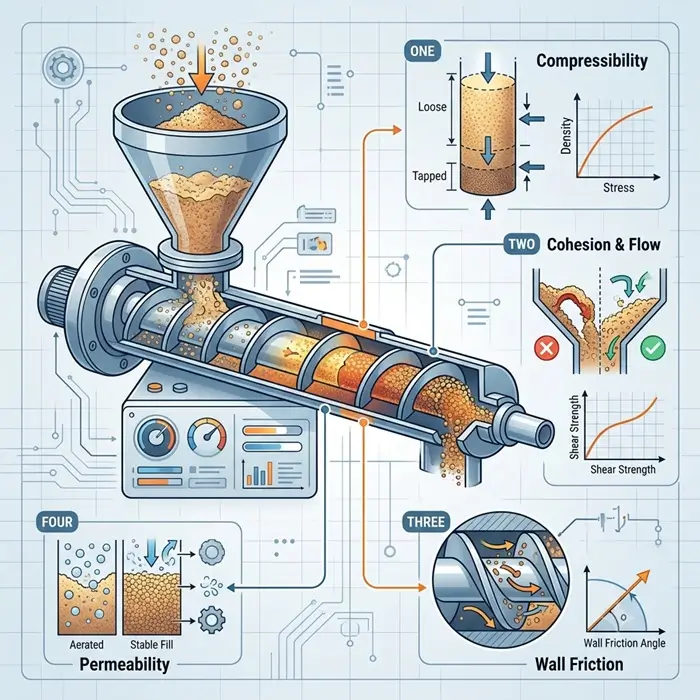
| Capacity and calibration | Bulk density and compressibility | Fresh, settled, and relevant consolidated states | Working volume and sensitivity to state | Mass per revolution and practical capacity in the feeder |
| Inlet supply | Shear and wall-friction measurements | Relevant low loads, surfaces, and time at rest | Hopper and supply assessment | Actual extraction and agitation response |
| Refill behavior | Permeability and deaeration | Actual transfer history and waiting times | Gas movement and state-change assessment | Refill transient using independent output measurements |
| Product preservation | PSD and morphology; strength and attrition | Inlet/outlet samples; worst credible mechanical duty | Damage, segregation, and contamination risk assessment | Product specifications over campaign duration |
| Environmental envelope | Moisture response; surface behavior | Expected humidity, temperature, and contact materials | Conditioning and cleanability requirements | Deposits and repeatability after prolonged operation |
| Delivery acceptance | Timed catch tests or suitable independent receiving-scale records | Each rate; multiple refill/start/stop cycles and representative lots | Bias, variability, cumulative error, and dose repeatability | Transfer of results to installed conditions and control settings |
Verification and acceptance
Agree pass criteria before testing
Define project-specific numerical limits and the measurement procedure before running a trial. Keep raw records alongside processed results.
Integration
Make the weighing and material boundaries explicit
Review the installation as a connected system, including stopped and abnormal states.
When a problem already occurs
Use the diagnostic route
For an installed process, start with Feeding, Dosing and Batching Variation or Poor Flow and Discharge. Use the findings to define the equipment or operating change that needs verification.
Go Deeper
Read the supporting technical articles
Explore the material mechanisms behind feed variation.


Technical FAQ
Feeding and dosing questions
Use these boundaries when comparing proposals.
Technical basis
Sources and scope
<p>Use material-characterization methods and an agreed equipment acceptance protocol together. No single material test establishes feeder performance.</p>
- Fathollahi et al. (2024), Improving Continuous Loss-in-weight Feeding Accuracy by a Novel Hopper Design: experimental evidence that hopper geometry, compressibility, and refill conditions affect performance; the tested configuration does not establish a universal design.
- ASTM D6128-22 and ASTM D6773-22: apparatus-specific bulk-solids shear testing for relevant supply and wall-contact questions. These are not feeder-accuracy acceptance standards.
- Engisch and Muzzio (2012), Method for characterization of loss-in-weight feeder equipment: a methodology for evaluating feeder performance across powders, tooling, and operating setpoints. Relevant to performance characterization and feeder trials.
- Engisch and Muzzio (2015), Feedrate deviations caused by hopper refill of loss-in-weight feeders: assessment of refill-related delivery deviations, supporting separate evaluation of refill performance rather than relying only on steady-state averages.
- OIML R 61-1 (2017), Automatic gravimetric filling instruments: Metrological and technical requirements and OIML R 61-2 (2017), Test procedures: requirements and procedures covering individual fill mass, variation, and preset-value error. Relevant where batch-filling equipment falls within their scope; these are not general continuous-feeder accuracy standards.
Define feeder acceptance through a documented test protocol covering the actual materials, rates, time scales, refill cycles, measurement uncertainty, and installation conditions. Use applicable sector-specific requirements where the duty demands them.
Need the material data behind the design decision?
Define the feed duty, material range, and unresolved delivery question before commissioning characterization. Delft Solids Solutions can discuss the relevant testing scope. Contact the laboratory with the application and sample information; agree separately who will verify feeder performance and equipment integration.