

Process & Equipment
Conveying & Transfer
Move the material while preserving its required condition
Specify the transfer duty, route, material envelope, and required condition at the destination.
Compare pneumatic and mechanical principles, then verify capacity, product integrity,
containment, and the complete receiving cycle.




Jump to
Jump to a specific engineering decision, or follow the sections from process requirements through equipment selection and verification.
Key Takeaway
Specify the transfer and the arrival condition
Choose a conveying system around the required throughput, physical route, powder behavior, and acceptable product change. Pneumatic regime, mechanical loading, pickup, and receiving equipment must work together across the complete cycle. Verify particle integrity, composition, residual material, and containment as well as transfer rate. Neither a successful delivery nor a dense-phase label establishes that the system meets the product requirement.
Start with the requirement
Define what the transfer must achieve
Specify performance at the destination and include the operating time available to achieve it.
Powder constraints
Identify what limits transport
Use material measurements to define trial conditions and exclude unsuitable options.
Choose by application question
Start with the limiting decision
Select the unresolved requirement before comparing equipment proposals.
Transport principle
Compare the complete transport system
Pneumatic transport uses a gas stream and requires material entry, a conveying line, gas-solid separation, and a gas mover. Mechanical conveyors move material using a screw, belt, chain, cable, buckets, or vibratory motion. Gravity transfer uses available elevation but still needs controlled entry and discharge.
Compare routing, energy, wear, access, and cleaning alongside capital cost. A short direct mechanical route may be attractive where a pneumatic circuit would require substantial ancillary equipment. Conversely, a pipe route may fit a constrained installation better than a conveyor structure. Assess the actual layout rather than treating either family as universally superior.
Decision output: Define the candidate principle and its system boundary, including all drives, gas handling, supports, controls, and receiving equipment.
Pneumatic regime
Separate pressure direction from solids flow structure
Pressure and vacuum describe the driving pressure arrangement. Dilute and dense phase describe the gas-solid transport regime. Pressure is not synonymous with dense phase, and vacuum is not synonymous with dilute phase.
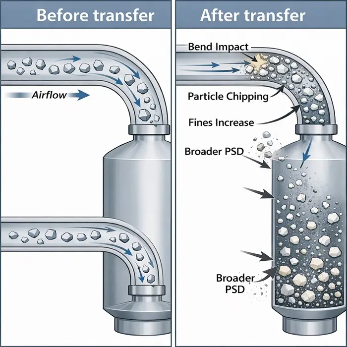
Dilute-phase systems normally rely on particles being transported in suspension. Dense-phase systems use more concentrated structures that depend on the material and equipment. Lower gas velocity can reduce some impact damage, but friction, compression, unstable plugs, or inlet hardware can still damage the product. Do not convert a dilute-phase line to dense phase merely by reducing air.
Decision output: Confirm the available stable operating region through relevant material evidence, conveying trials, and design calculations; avoid a universal velocity or solids-loading cutoff.
Route design
Assess the whole route, not one nominal velocity
For pneumatic transfer, calculate pressure losses and local gas conditions along horizontal and vertical sections, bends, valves, and the receiver. Superficial gas velocity is actual volumetric gas flow divided by pipe area; it is not particle velocity. State pressure and temperature when reporting flow.
For fixed gas mass flow, changes in gas density and pipe area change velocity along the line. Check both pickup and downstream sections rather than relying on inlet velocity alone. For mechanical transport, assess loading, inclination, drive duty, transfer points, and loaded starting conditions. Changes in route require reassessment of capacity and product exposure.
Decision output: A route-specific design with operating margins, access for maintenance, and a documented basis for extrapolating trial results.
Product integrity
Measure what changes during transfer
Set acceptable changes in PSD, fines, shape, coating integrity, and composition before testing. Damage can occur at entry, bends, mechanical clearances, discharge, and separation, not just in the main conveying length.
Compare representative inlet and outlet samples. Where segregation matters, sample across receiver filling and drawdown instead of relying only on a combined batch. Distinguish single-pass effects from cumulative changes in recirculating test loops. A lower measured fines fraction may reflect fines captured elsewhere rather than reduced attrition.
Decision output: A qualified operating range supported by product-quality measurements and a mass balance that accounts for receiver product, collected fines, and residual material.
Pickup and receiving
Match the interfaces to the transfer cycle
Define how material enters the conveyor and whether supply is controlled or flood-fed. An inlet device must provide the required feed without unacceptable gas leakage, surging, or damage. Coordinate metering requirements with Feeding & Dosing.
Size receiver working capacity, separation, filter duty, venting, and discharge around the incoming gas and solids load. Check whether discharge interrupts collection and whether the next process needs deaerated powder or a buffer. An intermittent receiver can limit system throughput even when the line has sufficient instantaneous capacity.
Decision output: A complete cycle and interface specification, including destination availability, filter condition, residual inventory, and downstream material state.
Containment and cleanability
Define the containment boundary and cleanout method
Specify the required enclosure, leakage performance, gas quality, product-contact materials, and residue limits. Vacuum can favor inward leakage in negative-pressure sections, but it does not demonstrate containment during discharge, filter handling, or maintenance.
Provide access to retained-product locations and define cleaning verification. Assess conveying-gas moisture and temperature where they can change the powder. Address combustible dust, ignition sources, static electricity, pressure, and isolation through the applicable specialist hazard assessment. A sealed conveyor is not automatically an explosion-protected system.
Decision output: A verifiable containment and cleaning specification with clear responsibility for hazard controls and maintenance access.
Selection comparison
Compare principles and their boundaries
Compare alternatives using the complete duty, including pickup and receiving equipment.
Principle |
Best fit |
Critical powder inputs |
Strength |
Limitation and integration check |
|---|---|---|---|---|
| Dilute-phase pneumatic | Route flexibility with a material that can be suspended | Size, density, cohesion, attrition sensitivity | Broad application range; enclosed pipe routing | Gas demand, bend impact, receiver/filter duty; verify local velocities and arrival condition |
| Dense-phase pneumatic | Material and equipment supporting stable concentrated transport | Permeability, air retention, size distribution, strength | Potential reduction in velocity-related damage | Feasibility is material-dependent; verify plugs, pressure loads, clearing, and restart |
| Screw conveyor | Direct enclosed horizontal or inclined transfer | Bulk density, flow, abrasiveness, adhesion | Compact transfer path and accessible mechanical options | Incline and loading affect capacity; evaluate shear, wear, deposits, and loaded starting |
| Belt conveyor | Route suited to a supported material bed | Particle size, bulk density, particle shape, surcharge behavior, spillage tendency, and dustiness | Limited relative motion within a stable bed | Transfer-point drops, belt cleaning, spillage, enclosure, and footprint |
| Drag / tubular drag | Enclosed route suited to chain or cable transport | Particle size, fragility, adhesion, bulk density | Controlled mechanical movement through an enclosure | Bends, clearances, chain/cable wear, retained product, and cleaning access |
| Bucket elevator | Predominantly vertical lift | Flow, particle strength, adhesion | Compact vertical transport | Filling and discharge damage, carryback, boot residue, tracking, and protection |
| Vibratory conveyor | Suitable material on a defined tray route | Flow, shape, fragility, adhesion | Accessible conveying surface; controllable transport | Vibration transmission, noise, loading sensitivity, and enclosure |
| Gravity chute | Available elevation with controlled flow | Wall friction, cohesion, size, impact sensitivity | No transport drive along the chute | Outlet control, dust entrainment, segregation, wear, and impact at discharge |
Operating window
Specify stable transport and acceptable product change
Qualify settings against both delivery and material quality.
Variable | Define and monitor | Boundary check |
|---|---|---|
| Solids throughput | Minimum, normal, peak rate and batch cycle | Stable pickup, receiver capacity, and delivered mass |
| Pneumatic gas flow | Mass flow or volume with stated reference conditions | Local velocities, pressure demand, leakage, and clearance of the line |
| Solids loading | Solids-to-gas mass-flow ratio where applicable | Stable regime for this material and route |
| Mechanical duty | Speed, fill/loading, inclination, drive load | Capacity, damage, wear, and restart torque |
| Receiver condition | Working volume, filter pressure drop, discharge timing | Collection and discharge without loss of containment or throughput |
| Material condition | PSD, moisture, temperature, density, and aeration | Performance at credible material extremes |
| Stop and restart | Clearance sequence, residual loading, approved recovery | No uncontrolled restart into a blocked or unavailable destination |
Data before design or scale-up
Request measurements that support the choice
Characterization narrows options; representative equipment trials and calculations establish design performance.
Design decision | Evidence | Conditions to reproduce | What it supports | What remains |
|---|---|---|---|---|
| Capacity and loading | Bulk density and packing | Incoming, settled, and relevant consolidated states | Volumetric duty and working inventory | Conveyor loading and complete-cycle throughput |
| Pickup and discharge | Shear and wall-friction tests | Relevant surfaces, stress, time at rest | Supply and chute/hopper assessment | Actual extraction and mechanical passage |
| Pneumatic feasibility | Permeability and deaeration | Actual transfer conditioning and material variability | Gas-interaction assessment | Trial conveying map and route-specific pressure calculation |
| Product preservation | Strength and attrition; PSD and morphology | Relevant impact/shear exposure; before/after samples | Damage sensitivity and measurable quality change | Representative route, repeated exposure, and full mass balance |
| Containment and environment | Dustiness; moisture response | Actual product condition and gas exposure | Dust-release and environmental sensitivity | Installed containment and specialist hazard assessment; dustiness does not establish explosibility |
| Blend preservation | Representative composition sampling during filling and drawdown | Real transfer cycle and receiver geometry | Detection of time-dependent segregation | Sampling uncertainty and full-scale distribution |
| Design verification | Conveying trials with measured solids rate, gas/drive demand, pressure, and quality | Representative material, route elements, start/stop states | Operating envelope and design model calibration | Documented scale-up assumptions and commissioning checks |
Verification and acceptance
Agree numerical acceptance limits before trials
Record material, route, settings, measurement uncertainty, duration, and deviations. Assess the whole cycle rather than selecting only a stable interval.
Integration
Specify each interface and its owner
The transport system begins at material pickup and ends when the receiving process can use the product.
When a problem already occurs
Use the diagnostic route
For an installed system, use Attrition, Breakage and Wear, Segregation and Blend Inconsistency, or Poor Flow and Discharge. Use the findings to define the equipment or operating change that needs verification.
Go Deeper
Read the supporting technical articles
<p>Explore conveying mode, particle damage, and system design.</p>


Technical FAQ
Conveying and transfer questions
Use these boundaries when reviewing an equipment proposal.
Technical basis
Sources and scope
Use system-specific engineering references together with representative material and conveying evidence. Manufacturer guidance supports principles and trial planning, not independent proof of a proposed installation.
- Coperion, Dense phase versus dilute phase conveying: manufacturer explanation of the two transport regimes; product suitability and damage require application-specific verification.
- Jenike & Johanson, Pneumatic Conveying Testing: direct engineering account of testing minimum conveying velocity, pressure drop, and solids loading; supports representative trial design.
- KWS, Screw Conveyor Engineering Guide: mechanical design guidance linking material condition, capacity, route, power, and torque; use within its stated equipment scope.
- Coperion, Important Considerations for Dilute Phase Conveying (2025): system components, material characteristics, and pneumatic operating considerations; stated example ranges are not universal design limits.
- Coperion, Avoiding dust in pneumatic conveying systems: manufacturer discussion of velocity-related pellet damage and contact with pipeline components; material-specific rather than a guarantee for all powders.
- David Mills, Pneumatic Conveying Design Guide, third edition: independent engineering reference covering conveying modes, material influences, feeding and receiving equipment, pipeline design, scale-up, and particle degradation. Apply its design methods with representative conveying data and the actual route constraints.
- Don McGlinchey (ed., 2008), Bulk Solids Handling: Equipment Selection and Operation: independent reference covering equipment selection, mechanical conveying, and operating limitations. Supports assessment of equipment suitability; belt conveying is explicitly outside this volume’s scope.
Agree a documented acceptance protocol for the intended materials, route, operating cycle, sampling plan, and uncertainty. Apply the relevant equipment, pressure, dust-hazard, and sector requirements through the responsible design disciplines.
Need the material data behind the design decision?
Define the transfer duty, material range, and required arrival condition before commissioning characterization. Delft Solids Solutions can discuss the relevant testing scope. Contact the laboratory with the application and sample information; agree separately who will design and verify the conveying system.
