
Troubleshooting

Attrition, breakage and wear

Particle damage and equipment wear must be separated because both can create fines and contamination
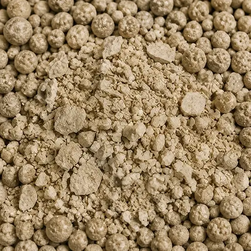
Illustration of attrition, breakage and wear in powder processing.

Map the change across each handling step. Compare particle size, morphology, product function, and wear debris before and after the suspected operation, then relate damage to impact, sliding, compression, velocity, and residence time.

Troubleshooting

Attrition, breakage and wear

Particle damage and equipment wear must be
separated because both can create fines and
contamination

Map the change across each handling step. Compare particle size, morphology,
product function, and wear debris before and after the suspected operation,
then relate damage to impact, sliding, compression, velocity, and residence time.


Icon representing observed attrition, breakage and wear patterns

By what you see

Look for a growing fine tail, chipped or rounded particles, coating loss, changed performance, or wear debris.

Icon representing changed process or material conditions

By what changed

Look for changes in velocity, impact, solids loading, equipment settings, batch, PSD, composition, or recycle.

Icon representing likely attrition, breakage and wear mechanisms

By likely mechanism

Separate impact fracture, surface abrasion, compression damage, agglomerate breakup, and equipment erosion.

Icon representing relevant diagnostic measurements

By measurement route

Use PSD, morphology, strength, and debris analysis to separate particle damage from equipment wear.

Find your route

Start with the observed failure, then add context

Map the change across each handling step. Compare particle size, morphology, product function, and wear debris before and after the suspected operation, then relate damage to impact, sliding, compression, velocity, and residence time.

  1. 1Observation
  2. 2Change or context
  3. 3Route

Step 1  What are you seeing?

Step 2  What changed, or when does it happen?

The same attrition, breakage and wear pattern can come from a different mechanism after refill, storage, conveying, a humidity shift, or a change in the powder itself.

Step 3  Your diagnostic route

Quick diagnostic comparison

Separate the leading routes before changing the process

Use the pattern and event history to select the first discriminating measurement. The table is a triage aid, not a substitute for reproducing the failed state.

Use the observed pattern and the change that preceded it to select the first discriminator. The pattern does not prove the mechanism.

What you observeWhat changedLikely mechanismMeasurement that separates it
The fine tail grows through the processAfter pneumatic conveying and receiversImpact fractureStagewise PSD: Where does the fine tail or oversize population change?
Particles round, chip, or lose a coatingAfter feeding and dosingSurface abrasionMorphology and surface: Is the change fracture, abrasion, coating loss, or deagglomeration?
Metallic or polymeric debris appearsAfter milling and classification settings or contact surfaces changedCompression damageWear-debris chemistry: Does debris match product, liner, seal, or tool material?
Function changes with little median-size shiftWith a changed batch, PSD, composition, or recycle fractionEquipment erosionStrength under representative loading: Which impact or compression level initiates damage?

Use the measurement under the material state and process conditions that produced the failure.

Likely mechanisms

Separate particle damage from equipment wear and deagglomeration

Locate the first stage where particle size, morphology, coating condition, product function, or foreign debris changes. Then match the pattern to the loading mode that could create it.

Impact fracture

High-velocity collisions exceed particle strength and create angular fragments or a growing fine tail.

Separate it with: stagewise PSD and morphology at impact locations.

Compression damage

Screws, rolls, valves, plugs, or constrained beds can crush fragile particles when local load exceeds particle strength.

Separate it with: representative compression or strength testing and stagewise PSD.

Equipment erosion

Particles can wear liners, pipes, seals, or tools, creating foreign debris and gradually changing the contact geometry.

Separate it with: wear-debris composition and inspection of the relevant contact surfaces.

Surface abrasion

Repeated lower-energy contact removes asperities, coatings, or weak surface layers without necessarily fracturing the whole particle.

Separate it with: fines generation plus surface, coating, and morphology comparison.

Agglomerate breakup

Weak clusters can separate into their constituent particles without fracture of the primary particles themselves.

Separate it with: dispersion-state, PSD, and microscopy comparison before and after handling.

Diagnostic note

A higher fines fraction does not prove attrition.

An apparent increase in fines can also come from deagglomeration, segregation, sampling bias, or a changed incoming lot. Confirm where the shift first appears and whether particle morphology changes.

Measurement routes

Measure the change, then reproduce the loading mode

Choose measurements that show where the particle population changed and whether the suspected stress can reproduce the same damage mechanism.

Particle size and morphology

Map PSD, fragment shape, edge rounding, coating loss, or deagglomeration before and after the suspected step.

Strength and attrition response

Reproduce impact, abrasion, compression, or repeated handling at a representative stress or energy level.

Wear debris and composition

Identify foreign material when equipment erosion, liner wear, seal damage, or tool contact may be contributing contamination.

Process context

Where the damage appears changes what to check first

Keep velocity, impact, sliding distance, compression, residence time, and repeated handling attached to the location where the change first appears.

01

Conveying and transfer

Velocity, bends, valves, and solids loading set repeated impact and sliding exposure.

02

Feeding and dosing

Screws, agitators, clearances, and refill behavior can crush or abrade fragile particles.

03

Size reduction and classification

The intended breakage operation can overproduce fines, damage coatings, or wear.

04

Mixing and blending

Extended mixing, high tip speed, or repeated particle-wall contact can erode fragile granules or coatings.

05

Storage and discharge

Consolidation, plugs, outlet restrictions, and discharge impacts can add compression or impact damage late in handling.

06

Filling and packaging

Drops, repeated transfers, and container handling can damage fragile granules after the main process is complete.

Go deeper

Guides and articles for attrition, breakage and wear

Use the deeper technical material to identify how particles are being damaged, distinguish product attrition from equipment wear, and choose the most useful next measurement or process route.
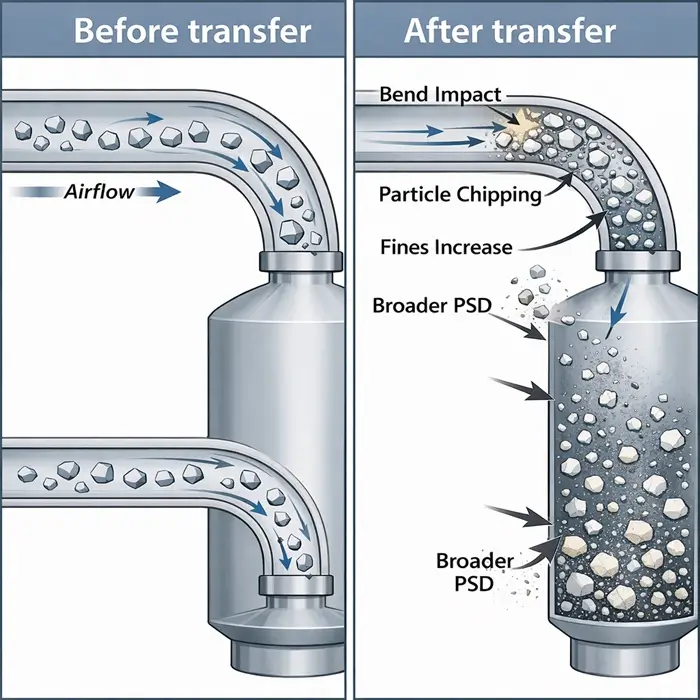
Coated particle damage before particle size changes

Pneumatic Conveying Attrition: Transfer Quietly Changes Powder

Pneumatic conveying attrition can change a powder even when the transfer looks successful, and the material may still arrive with more fines.

Dense-phase and dilute-phase pneumatic conveying attrition and segregation

Dense-Phase vs Dilute-Phase Pneumatic Conveying: Attrition & Segregation

Compares how velocity, solids loading, and particle-wall versus particle-particle contact change attrition risk between dilute- and dense-phase conveying.

Technical illustration comparing fines content with powder dust release behavior

Powder Dustiness Is a Release Problem, Not a Fines Number

Explains why a growing fine fraction can increase airborne release without making dustiness a particle-size result.

Understand attrition

Explore the Particle Behavior child for mechanisms controlling particle wear, breakage, and fines generation.

Browse attrition articles

Browse PTI articles covering attrition, abrasion, particle breakage, and handling-induced fines generation.

Choose damage tests

Compare Test Methods for particle strength, fracture, abrasion, attrition, and related mechanical damage.

Dust and fines

Use the related Troubleshoot route when fines generation or airborne release is the visible plant problem.

FAQ

Attrition, breakage and wear questions

Attrition damages particles or granules through fracture, abrasion, or compression. Deagglomeration can increase the fine or small-particle population simply by separating weak clusters without breaking the primary particles. Compare PSD with morphology and dispersion state before and after the suspected step.
No. A higher measured fines fraction can also result from deagglomeration, segregation, sampling bias, or a different incoming particle population. Locate the first process stage where the shift appears and check whether morphology changes at the same point.
Impact fracture occurs when collisions exceed particle strength and create chips or angular fragments. Surface abrasion is usually a lower-energy, repeated-contact mechanism that rounds edges, removes coatings, or generates fine wear material from the surface.
Compare particle changes with the composition of any foreign debris and inspect the relevant contact surfaces. If debris matches a liner, seal, pipe, tool, or other equipment material, equipment erosion is implicated rather than product attrition alone.
Start with stagewise particle-size distribution and morphology to locate where the particle population changes. Add representative strength or attrition testing to reproduce the loading mechanism, and composition analysis when equipment wear or foreign debris is suspected.
Particles can collide with bends, walls, valves, and one another at velocities high enough to fracture or abrade fragile material. Solids loading, line geometry, residence time, and particle strength all influence the result, so compare material immediately before and after the conveying step.

Independent diagnostic support

Need the measurement, not just the guidance?

PowderTechnology.info works closely with Delft Solids Solutions, a contract research organization specializing in the physical behavior of powders and granules. DSS provides contract testing and characterization, with its laboratory working in accordance with ISO 17025. Contact Delft Solids Solutions.