
Test methods
Mechanical Strength, Attrition and Caking
Separate particle damage from strength developed during storage
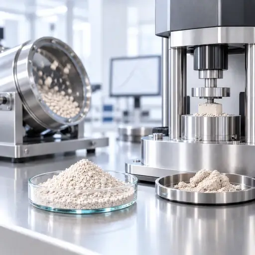
Granules can fracture, wear at their surfaces, or lose coatings during handling. A powder bed can also gain strength while stored under load, humidity, or temperature exposure. Choose the test by the stress mode, damage endpoint, and conditioning history behind the process question.
Test methods
Mechanical Strength, Attrition
and Caking
Separate particle damage from strength developed
during storage
Granules can fracture, wear at their surfaces, or lose coatings during handling.
A powder bed can also gain strength while stored under load, humidity, or
temperature exposure. Choose the test by the stress mode, damage endpoint,
and conditioning history behind the process question.




Select a method
Choose the stress or storage response you need to investigate
Seven routes cover individual-particle failure, repeated wear, impact, gas-driven attrition, and conditioned bulk strength. Storage conditioning must be followed by an explicit measurement endpoint.
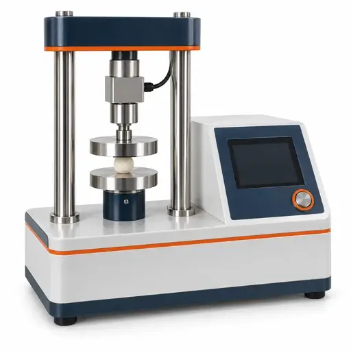
Single-particle or granule compression
Compress individual specimens between aligned platens while recording force and displacement.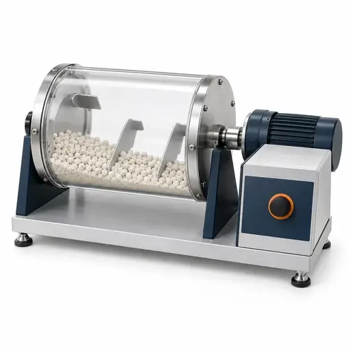
Tumbling attrition and friability
Expose an ensemble of granules to repeated rolling, rubbing, lifting, and dropping in a specified drum.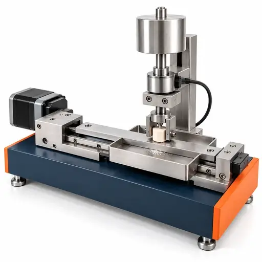
Controlled particle abrasion
Hold a robust pellet against a defined counterface under controlled normal load and sliding motion.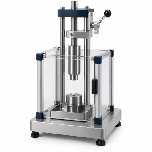
Controlled impact breakage
Apply a defined impact to a particle or small specimen and recover the resulting fragments.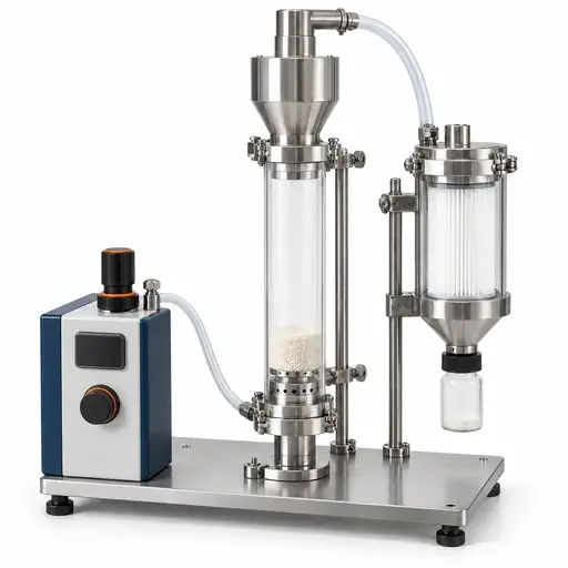
Air-jet attrition
Use controlled gas jets to stress a powder sample and collect elutriated fines over a defined exposure.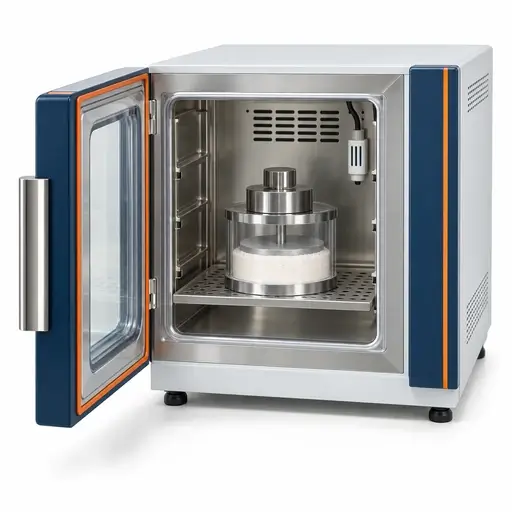
Controlled caking and blocking conditioning
Expose a powder or granular bed to a defined storage history before measuring its resistance to breakup or separation.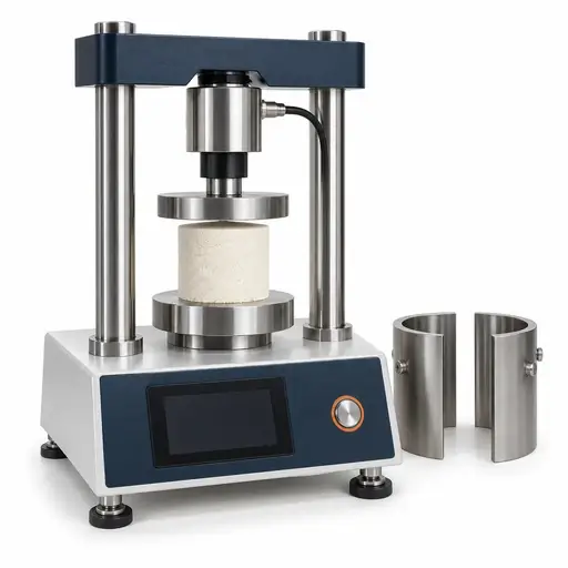
Bulk cake strength and unconfined failure
Load a conditioned cylindrical powder cake axially after removing lateral confinement and record its failure.Core concept
Damage and caking need different tests
Particle strength describes the response of an individual granule, pellet, or particle to a defined load. Attrition is progressive particle degradation and can include surface abrasion, chipping, and fracture. The same fines percentage can therefore result from different damage mechanisms.
Bulk caking is strength development in a collection of particles. Mechanical consolidation, moisture-mediated contacts, solid bridges, and temperature-dependent changes can contribute. Individual granules may remain intact while their contacts form a strong cake. Conversely, strong granules may shed coatings or surface fines during transport.
Key takeaway
Match the stress and the damage endpoint
Use single-particle compression for crushing resistance, tumbling for repeated handling damage, controlled abrasion for sliding wear, and impact or air-jet testing when those stresses dominate. For storage problems, condition the material under representative load, time, humidity, and temperature before measuring cake strength. Report newly generated fines separately from pre-existing fines and distinguish coating loss, fracture, and bulk strength development. Laboratory rankings support material and process comparisons only within the tested stress history; they do not directly predict transport damage or shelf life without process validation.
What controls it
Six decisions define a useful damage or caking test
<p>Define the process event and failure criterion before selecting the apparatus.</p>
Selection and interpretation
The same fines percentage can hide different mechanisms
Keep initial and final fines on a stated mass basis and report the cutoff, recovered mass, and separation procedure. A smaller particle size can indicate fracture, surface loss, or deagglomeration. Examine particle shape and surfaces before assigning the mechanism.
Engineering question | Primary route | Useful output | Critical boundary |
|---|---|---|---|
| Will individual granules crush? | Single-particle or granule compression | Failure-load distribution | Match size, orientation, and loading rate |
| Does repeated handling generate fines? | Tumbling attrition and friability | Fines or mass loss versus exposure | Separate initial fines and record mass recovery |
| Is material wearing from the surface? | Controlled particle abrasion | Wear and coating changes | Distinguish surface loss from fracture |
| Does a collision fragment the particles? | Controlled impact breakage | Breakage probability and fragment sizes | Define impact conditions and support |
| How does the powder resist jet-driven attrition? | Air-jet attrition | Collected fines and method index | Separate damage from aerodynamic collection |
| What storage history promotes caking? | Controlled caking and blocking conditioning | Conditioned samples and paired endpoint | Conditioning alone is not strength measurement |
| How strong is the resulting bulk cake? | Bulk cake strength and unconfined failure | Failure force or qualified nominal stress | Control geometry, demolding, and failure mode |
How to measure it
Select the method by the evidence the decision requires
The method sections below separate principle, sample state, preparation, output, limitation, disagreement, and decision use. Use the image selector above to jump directly to a method.
Test method 01
Single-particle or granule compression
Measurement principle: Compress individual specimens between aligned platens while recording force and displacement.
Suitable sample state: Representative granules or pellets tested individually within defined size and shape classes.
Sample preparation: Control orientation, platen contact, load rate, instrument compliance, moisture, and specimen count. Record dimensions and the failure criterion.
Test method 02
Tumbling attrition and friability
Measurement principle: Expose an ensemble of granules to repeated rolling, rubbing, lifting, and dropping in a specified drum.
Suitable sample state: A representative granular sample with a measured starting size distribution.
Sample preparation: Specify drum geometry, baffles, fill mass, speed, revolutions, conditioning, and fines separation. Measure the initial fines and use a controlled post-test separation procedure.
Test method 03
Controlled particle abrasion
Measurement principle: Hold a robust pellet against a defined counterface under controlled normal load and sliding motion.
Suitable sample state: Pellets or granules that can be held reproducibly without damage from the fixture.
Sample preparation: Define holder, exposed surface, counterface material and finish, load, speed, sliding distance, debris recovery, and environmental conditions. Check the fixture for damage to the specimen.
Test method 04
Controlled impact breakage
Measurement principle: Apply a defined impact to a particle or small specimen and recover the resulting fragments.
Suitable sample state: A representative particle population tested at controlled size, orientation, and condition.
Sample preparation: Specify striker or target geometry, impact mass and velocity or calibrated drop conditions, support, repetitions, and fragment recovery. Document the impact event rather than drop height alone.
Test method 05
Air-jet attrition
Measurement principle: Use controlled gas jets to stress a powder sample and collect elutriated fines over a defined exposure.
Suitable sample state: A powder population suited to the specified jet apparatus, gas conditions, and collection system.
Sample preparation: Control sample conditioning and mass, nozzle geometry, gas flow and pressure, duration, collection intervals, and filter recovery. Apply the specified initial-fines treatment and calculation.
Test method 06
Controlled caking and blocking conditioning
Measurement principle: Expose a powder or granular bed to a defined storage history before measuring its resistance to breakup or separation.
Suitable sample state: Representative material in a conditioning cell or relevant contact arrangement.
Sample preparation: Specify load, time, temperature, relative humidity, initial moisture, cell and liner, moisture-exchange boundary, and exposure cycles. Include an unaged reference and distinguish sealed from open conditioning.
Test method 07
Bulk cake strength and unconfined failure
Measurement principle: Load a conditioned cylindrical powder cake axially after removing lateral confinement and record its failure.
Suitable sample state: A reproducible freestanding cake made under defined consolidation and environmental conditions.
Sample preparation: Control cake dimensions, density, conditioning, mold release, platen alignment, loading rate, and time between removal and testing. Record specimens damaged during release.
Conditional routes
Extend the test when the failure mode requires it
Add these routes when coating function, storage shear, specimen fragility, or process geometry remains unresolved.
Coating damage without size change
Add microscopy, surface inspection, or an application-relevant release measurement when particles remain intact but the coating loses function.
Time-consolidated shear
Use a suitable shear-cell route when storage strength must support hopper-flow or arching assessment rather than cake breakup alone.
Weak cakes and blocking
Use a validated penetration, shear, or separation endpoint when the specimen cannot be demolded intact. Report the boundary condition and avoid comparing unlike strength numbers.
Representative handling trials
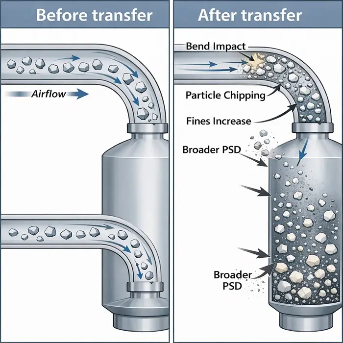
Use a conveying loop or transfer trial when line geometry and repeated passes are central. Compare before and after samples with mass recovery and operational conditions recorded.
Where it matters
Connect laboratory damage to the operating step
<p>Use a test ranking to choose a focused process trial, not as a direct prediction of damage throughout an entire line.</p>
Technical FAQ
Common questions about damage and storage strength
<p>Check the stress, starting population, and endpoint before comparing the numbers.</p>
Go deeper
Explore transport damage and powder caking
Continue with three published PTI articles connecting mechanical testing to handling and storage.
Technical basis / sources
Standards and application boundaries
These standards address specific catalyst materials and apparatus. They are relevant examples, not universal procedures for all powders or all seven routes.
- ASTM D4179-22: single-pellet compression for regular formed catalysts and carriers; irregular shapes and extrudates are outside its scope.
- ASTM D4058-25: attrition and abrasion of catalysts and carriers within the specified size range.
- ASTM D5757-22: air-jet attrition of FCC catalysts, with material limits and FCC-specific precision.
- ASTM D8353-26: a guide to drop-breakage assessment of formed catalysts and catalyst carriers by dropping the sample through a specified pipe onto a steel plate. Relevant to impact durability, but not a procedure for the guided drop-weight fixture described here.
Controlled sliding, particle impact, storage conditioning, and cake failure require documented procedures appropriate to the specimen and decision. Record deviations from any cited standard, and do not claim conformity based only on similar-looking apparatus. The published PTI articles above supply application context; they do not replace the laboratory procedures.
Need the measurement, not just the guidance?
If the uncertainty concerns particle fracture, surface wear, fines generation, coating damage, or strength developed during storage, define the relevant stress and conditioning history before commissioning tests. Agree the sample preparation, damage cutoff, strength endpoint, mass recovery, and interpretation boundaries with the laboratory. PTI works closely with Delft Solids Solutions, a contract research organization specializing in the physical behavior of powders and granules. Contact Delft Solids Solutions.