Troubleshooting

Spreading and deposition
problems

Streaks, bare zones, ridges, and density variation
connect powder state to delivery, tool, and
substrate interaction
Treat the deposited layer or powder deposit as a process output,
not a direct proxy for bulk flowability. Separate feed delivery,
particle condition, spreading or deposition dynamics,
electrostatics, substrate condition, and tool interaction.


By what you see

By what you see

Repeatable streaks or bare zones appear; material piles ahead of the tool; layer density varies; or deposition drifts across a pass or build.

By what changed

By what changed

After feedstock conditioning or delivery; after speed, gap, tool, or substrate changed; or with changes in batch, PSD, morphology, charge, or recycle.

By likely mechanism

By likely mechanism

Delivery variation, agglomerates, cohesion and interlocking, electrostatic adhesion, segregation, or tool-surface interaction.

By measurement route

By measurement route

Choose measurements that separate feed delivery, particle condition, spreading dynamics, charge effects, and tool or substrate interaction.

Find your route

Start with the observed failure, then add context

Treat the deposited layer or powder deposit as a process output, not a direct proxy for bulk flowability. Separate feed delivery, particle condition, spreading or deposition dynamics, electrostatics, substrate condition, and tool interaction.
  1. 1Observation
  2. 2Change or context
  3. 3Route

Step 1  What are you seeing?

Step 2  What changed, or when does it happen?

The same layer defect can come from feed delivery, particle condition, tool interaction, surface state, or charge. Preserve the actual conditioning, replenishment, spreading, substrate, and reuse history.

Step 3  Your diagnostic route

Quick diagnostic comparison

Separate the leading routes before changing the process

Use the pattern and event history to select the first discriminating measurement. The table is a triage aid, not a substitute for reproducing the failed state.

Use the observed pattern and the change that preceded it to select the first discriminator. The same visible defect can come from the powder, feed system, tool, or substrate.

What you observeWhat changedLikely mechanismMeasurement that separates it
A repeatable streak or track follows the tool directionThe tool, gap, or coarse particle tail changed, or the track stays fixed across powder lotsTool interaction or oversize-particle jammingControlled powder/tool swap plus PSD and oversize inspection: Does the track move with the powder or remain with the tool?
Bare or underfilled regions appear after a passReservoir level, dosing, replenishment, or feed delivery changedFeedstock delivery variation or cohesion-driven short-feedDelivered mass and layer mapping: Is the same amount reaching each pass, and does the local deficit match the visible undercoverage?
Material piles ahead of, behind, or on the toolSpeed, gap, tool geometry, surface condition, humidity, or grounding changedCohesion, tool interaction, or electrostatic adhesionDynamic spreading or deposition trial: Does the defect change with speed, gap, tool condition, or charge control?
Layer thickness or density changes gradually across the depositBatch, PSD, morphology, recycle fraction, feed rate, or spreading conditions changedSegregation, packing variation, or inconsistent feedSpatial layer mapping plus PSD or composition: Does the gradient track local mass, packing, particle population, or composition?

Use the measurement under the material state and process conditions that produced the failure.

Likely mechanisms

Separate powder, delivery, charge, and boundary effects

Treat the deposited layer as a process output. Identify whether the defect follows delivered mass, particle condition, electrostatics, segregation, or the tool and substrate boundary before changing settings.

Tool or substrate interaction

Gap, speed, compliance, roughness, damage, or substrate condition creates a defect tied to the process boundary.

Separate it with: a controlled tool and substrate parameter matrix that changes hardware independently of the powder lot.
Cold Spray Powder Deposition: Particle Velocity, Oxide Layers, and Why Some Powders Won’t Bond

Agglomerates or oversize

Clusters or coarse-tail particles interfere with the effective gap, tool, nozzle, or contact zone and create local defects.

Separate it with: PSD with oversize retention, morphology, and direct inspection of the defect path.
Powder Spreading in Powder Bed Fusion: What Recoater Interaction Reveals About Layer Defects

Cohesion and interlocking

Fine, irregular, or rough particles resist rearrangement and can cause short-feed, ridging, or incomplete coverage.

Separate it with: conditioned flow plus a controlled dynamic spreading or deposition trial.
Powder Spreading in Powder Bed Fusion: What Recoater Interaction Reveals About Layer Defects

Feedstock delivery variation

The spreading or deposition step receives an inconsistent mass or volume of powder from one pass to the next.

Separate it with: delivered mass, replenishment history, and spatial layer-mass mapping.
Powder-Fed Laser Cladding: Why Stable Feed Rate Does Not Guarantee Stable Deposition

Electrostatic or surface adhesion

Charge or surface forces make powder remain on the tool, walls, or substrate instead of depositing where intended.

Separate it with: charge response, decay behavior, grounding, humidity, and surface-condition trials.
Single-Contact Electrification Testing: Isolating Charge Transfer Per Contact

Segregation or packing variation

Particle differences redistribute during motion, creating local changes in composition, thickness, density, or packing.

Separate it with: spatial layer mapping with PSD, morphology, or composition checks across the deposited layer.
Virgin-to-Reused Powder Blend Ratios in Aerospace PBF-LB Qualification

Measurement routes

Measure the uncertainty, not the visible defect

Select the route that most clearly separates material state, delivered mass, dynamic tool interaction, packing, and charge under the failed process conditions.

Feed delivery & layer mapping

Check whether each pass receives the same mass or volume and whether visible defects align with local thickness, density, or composition changes.

PSD, oversize & morphology

Check whether coarse particles, agglomerates, fines, satellites, or shape changes interfere with rearrangement or the effective gap.

Dynamic spreading or deposition

Reproduce the defect while varying feed rate, speed, gap, tool geometry, and substrate condition one factor at a time.

Electrostatic & surface response

Determine whether charge generation, dissipation, grounding, humidity, or surface condition changes pickup, adhesion, release, or deposition.

Process context

Where the defect appears changes what to check first

Keep feedstock conditioning, delivery, tool and substrate condition, repeated-pass exposure, and recycle history attached to the diagnosis.

01

Feedstock conditioning

Sieving, drying, blending, storage, and recycle history define the particle state presented to the layer-forming step.

02

Feed delivery & replenishment

Reservoir flow, dosing, and replenishment determine whether each pass receives a stable amount of material.

03

Spreading or deposition

Tool geometry, speed, gap, contact, and powder response determine local coverage, thickness, and uniformity.

04

Tool & substrate condition

Wear, roughness, contamination, compliance, temperature, or grounding can create defects tied to the process boundary.

05

Build or deposition cycle

Repeated passes, heat exposure, recovery, and changing bed or substrate condition can shift later-cycle behavior.

06

Recycle & reuse

Recovery, sieving, replenishment, and reuse can change PSD, morphology, fines, charge history, and spreadability over time.

Go deeper

Guides and articles for spreading and deposition failures

Use the deeper material to separate feedstock condition, layer formation, repeated reuse, and substrate interaction instead of treating every defect as a generic flowability problem.
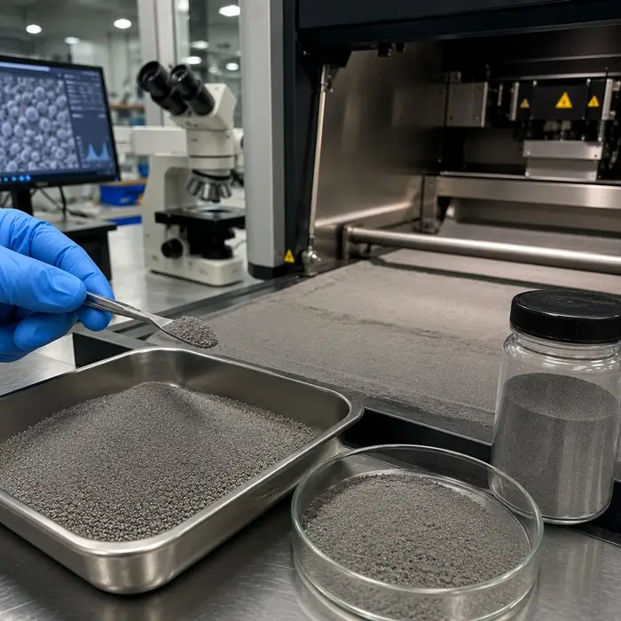
Metal powder feedstock and recoater-related spreading behavior

Powder Spreading in Powder Bed Fusion: What Recoater Interaction Reveals About Layer Defects

Separates streaking, short-feeding, layer nonuniformity, particle-size effects, powder cohesion, and recoater hardware into distinct diagnostic routes.

Virgin and reused powder blend for powder-bed fusion qualification

Virgin-to-Reused Powder Blend Ratios in Aerospace PBF-LB Qualification

Explains how reuse history, PSD shift, morphology drift, and replenishment change the powder population presented to repeated spreading cycles.

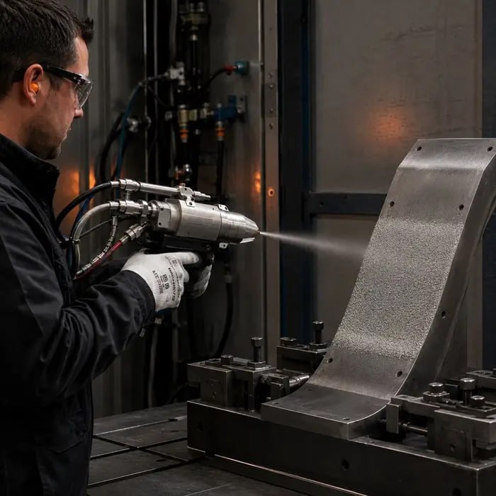
Cold spray nozzle depositing metal powder onto a substrate

Cold Spray Powder Deposition: Particle Velocity, Oxide Layers, and Why Some Powders Won’t Bond

Shows how particle state, velocity, surface oxide, and substrate interaction can determine whether a delivered powder stream actually becomes a deposit.

Particle size & morphology

Use the Test Methods family when oversize, agglomerates, fines, satellites, or morphology drift may be changing the effective spreading condition.

Electrostatics

Use the Test Methods family when pickup, adhesion, release, grounding, or charge dissipation changes across the tool or substrate.

Forming & densification

Follow the related Troubleshoot child when the layer is deposited consistently but density, compaction, cracking, or ejection becomes the next failure.

Process & equipment

Use the process hub when delivery hardware, spreading hardware, deposition equipment, or the substrate boundary is the dominant uncertainty.

FAQ

Spreading and deposition questions

No. The deposited layer is a process output created by the interaction of feed delivery, particle condition, tool or nozzle geometry, speed, gap, substrate state, electrostatics, and repeated-pass history. A powder can pass a bulk flow test and still spread or deposit poorly in the actual process.
Change the powder lot and tool condition independently while reproducing the same operating settings. A defect that stays fixed to the same tool position points toward wear, damage, or geometry. A defect that follows the powder lot or oversize population points toward particle condition.
The effective gap and rearrangement behavior can be controlled by the coarse tail, agglomerates, fines, satellites, and particle shape even when D50 remains unchanged. Review the full particle-size distribution and morphology rather than a single central value.
Not by itself. Bulk flow tests describe defined stress and motion conditions, while spreading is a dynamic interaction between a thin powder layer and specific hardware. Use bulk measurements as supporting evidence and reproduce the actual spreading or deposition step when possible.
Charge can alter pickup, retention, release, and adhesion on the powder, tool, walls, or substrate. Humidity, grounding, contact materials, surface contamination, and repeated contact can change both charge generation and dissipation, producing spatially nonuniform deposition.
Start with delivered mass or layer-thickness mapping and direct inspection of the defect pattern. Add particle-size and morphology checks when oversize or agglomerates are plausible, electrostatic measurements when adhesion or pickup changes, and controlled tool or substrate trials when the defect follows a process boundary.

Independent diagnostic support

Need the measurement, not just the guidance?

PowderTechnology.info works closely with Delft Solids Solutions, a contract research organization specializing in the physical behavior of powders and granules. DSS provides contract testing and characterization, with its laboratory working in accordance with ISO 17025. Contact Delft Solids Solutions.